CALL US TODAY

CALL US TODAY

cnc router cutting materials

The 11 Most Popular Types of CNC Machines

Computer numerical control (CNC) machining is a manufacturing process in which computers and software control how the machines manufacture parts.Ā Special CNC programs instruct different types of CNC machines on which motions to make for a desired shape, choosing the right tool, the speeds and feeds of the tooling, turning coolant on or off, and various other commands.

The computer language for programming CNC machines is a standardized language called ā€œG-code.ā€Ā  Visual programming tools called computer-aided manufacturing (CAM) software create the G-code.Ā  CNC machining is the method of choice when quality and precision are critical, parts and components are particularly complex, and repeatability is essential over long production runs.

What is a CNC Machine?

Before the technology that created computer-controlled machine tools was available, machinists used manually-controlled machines. Operators used handwheels and power feeds to direct the machining process along the X, Y, or Z-axis.

On the other hand, a computer controls servos operating the CNC machine and guiding it through the machining process.Ā  CNC machine tools allow for higher productivity because the machinery runs automatically without the attention of a full-time operator. Today, CNC machining is the dominant force in machining, while manual machines play a secondary role in lower-quantity work, repairs, and prototyping.

In the past, CNC machines were strictly in the industrial domain since their costs were out of reach for most one-person shops and hobbyists. However, there are now CNC machines for almost any budget, and DIYers are jumping on the bandwagon and buying them for their home shop.

Here are 12 of the most common types of CNC machines. Each performs somewhat different machining operations with few human errors, high-speed processes, and high-quality results.

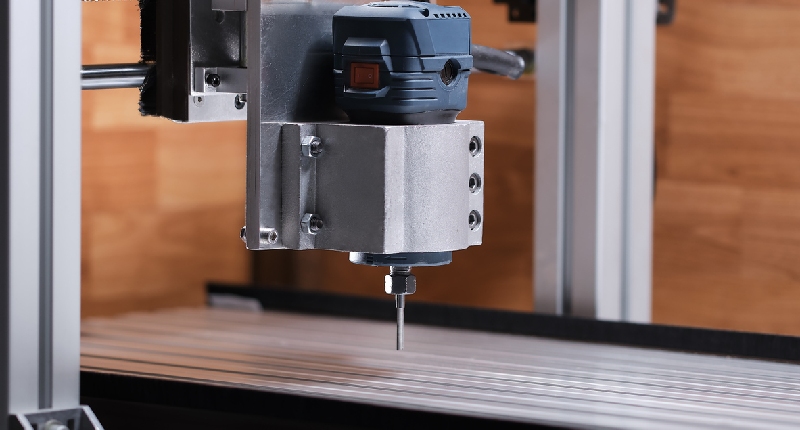
1. CNC Milling Machine

CNC milling machines use rotating cutting tools to remove material from a workpiece. The primary 3-axis CNC machines move along an X-axis (side to side), Y-axis (in and out), and Z-axis (up and down). These ā€œmillsā€ have been the backbone of machine shops and factories for many years and are used in manufacturing industries such as automotive, aerospace, medical, military, oil and gas, and precision engineering sectors where holding tight tolerances are required.

Sometimes referred to as CNC machining centers, the more advanced CNC machine tools can operate along up to twelve axes. These machines often have automatic tool changers, advanced machine coolant systems, pallet changers, and the latest software to improve the efficiency and accuracy of their machining processes.

2. CNC Lathe Machine

CNC turning mostly produces cylindrical parts by rotating a workpiece on a spindle and removing material with fixed cutting tools and drill bits. CNC lathe machines can be programmed to create various details on the rotating piece, making them the machine of choice for producing round parts, especially in large quantities where consistency, precision, and high production rates are paramount.

Although there are two types of CNC lathes, the horizontal style is the most popular. CNC horizontal lathe machining turns shafts, drums, and round parts. Depending on the length of the workpieces to be machined, these lathes can take up quite a bit of floor space.

On the other hand, CNC vertical lathes rotate the workpiece upright, allowing the spindle to cut at hard-to-reach angles. Vertical lathes have a smaller footprint and are ideal for turning larger, heavier workpieces.

3. CNC Router Machine

CNC routers can machine complex shapes from soft materials like wood, plastic, composites, and aluminum. These machines are limited to relatively thin materials, like plywood boards or sheet metal since their cutting tools have limited motion along the Z-axis. This limitation contrasts with CNC milling machines with an extended range of motion.Ā Ā However, like CNC mills, CNC routers use G-code to automatically move a high-speed rotating cutting tool to various coordinates to remove material from a workpiece.

CNC routers typically use a gantry-style construction with the spindle traveling left and right along the X-axis and back and forth on the Y-axis. Still, they are designed for something other than cutting complex harder metals, such as stainless steel. Instead, softer materials work better on gantry-style CNC routers since they are less ruggedly built than standard CNC mills.

4. CNC Electrical Discharge Machine (EDM)

CNC electrical discharge machines, or EDM, use a ā€œnon-contactā€ process that effectively machines parts despite their hardness. EDM involves placing an electrode or wire and electrically conductive materials into a circulating dielectric fluid. The fluid acts as an insulator until a specific spark gap and voltage ionize it, enabling a spark to travel to the workpiece.

Using CNC control, the electrode or wire moves as directed, rapidly turning the current on and off, helping to flush the material (swarf) from the workpiece.

There are two mainĀ types of EDM machines: sinker EDM and wire EDM machines.

Sinker EDMs use a copper or graphite electrode to create the shape, with the electrode machined to a mirrored image of the finished form in the workpiece. These electrodes can produce up to 30,000 electric sparks per second as they burn the shape.

Wire EDM feeds a strand of wire from a spool to the workpiece using a wire drive system. Electrical contacts energize the wire and pass through the workpiece at a feed rate determined by the material thickness and other factors.

Deionized water surrounds the wire, and electric sparks are continuously emitted along the length of the wire. Rollers pinch the wire and provide tension while guides above and below the workpieceĀ position the wire on its path. The EDM wires typically have diameters of 0.010ā€ to 0.012ā€ with thinner wires at 0.001ā€ to 0.004ā€.

5. CNC Plasma Cutting Machine

CNC plasma cutting is another method for slicing through metals with a plasma torch controlled by a computer program. Plasma cutters force gas or compressed air at high speeds through a nozzle. After an electric arc is added to the gas, ionized gas (plasma) is formed and cuts through the metal.

CNC plasma cutters are available in various sizes and prices, all able to cut through metal accurately and at speeds up to 500Ā inches per minute. Plasma cutters require a plasma gas and an assist gas to function, determined by the type of metal being cut.

6. CNC Grinding Machines

The term CNC grinding machine covers a significant territory, with cylindrical grinders, surface grinders, and centerless grinders covering most of it. CNC grinders automatically remove material using grinding wheels to improve surface finishes and meet tolerances that may not be possible through standard tooling on milling machines and lathes.

Cylindrical grinding machines consist of a spindle head that holds and rotates the workpiece while the grinding wheel moves across its surface, making various configurations such as tapers, steps, chamfers, grooves, and finished sizes on the outside or inside diameter of the workpiece.

Surface grinders generally work on flat surfaces to create the smoothest surface finishes possible or to ensure the accuracy and flatness of critical dimensionsā€”sometimes both.

In centerless grinding, the workpiece is held between two wheels, rotating in the same direction at different speeds. One grinding wheel is on a fixed axis and turns so that the force applied to the workpiece is directed downward. The centerless grinding processes allow parts to be held to tighter dimensional tolerances, achieve smoother surface finishes, and have high degrees of straightness.

7. CNC Laser Cutting Machine

Laser cutting is a fabrication process using a focused, high-powered laser beam to cut the material into various shapes. The materialā€™s melting, vaporizing, and burning occur after focusing the laser beam. The CNC laser cutter is appropriate for multiple materials, including metal, plastic, wood, and glass, and can produce precise and complex parts without special tooling.

There are several types of laser cutting, including oxidation, scribing, and fusion cutting. Each process makes parts with precision, accuracy, and high-quality edge finishes. There is less damage to the workpiece, less waste, and low power consumption with the laser cutting process.

8. CNC Drilling Machine

In simple terms, CNC drilling is a machining process mainly using drill bits to produce round holes in a stationary workpiece. The holes typically accommodate machine screws or bolts for assembly, so tolerances are not as tight as in other machining operations.

The CNC drilling process follows many steps as other CNC machining operations, including using CAD and CAM software, setting up the CNC machine and tooling, and assigning an operator to run and inspect the workpieces.

9. CNC Water Jet Cutters

A CNC water jet uses a high-pressure water system to cut various materials. Sometimes, water alone is sufficient to cut materials like wood and rubber. At other times, the water is mixed with an abrasive substance (like garnet or aluminum oxide) to cut more rigid materials.

The water jet operations are typically performed underwater to reduce the noise and mess from splashing. The water pressure is usually between 20,000 to 60,000 PSI, which is 30 times more pressure than a power washer, and it forces the water through a narrower nozzle of 0.010ā€ to 0.015ā€ in diameter.

Pumps and filters send the water into the CNC water jet unit. The filtering process is critical since only clean water can attain the ultra-high pressure required for a consistent cutting stream. Filtering also protects the unitā€™s parts, although sometimes a water treatment system is needed if the water contains harmful minerals.

10. 5-Axis CNC Machines

5-axis CNC machines allow a cutting tool to move in five different directions ā€” X, Y, Z-axes, and A and B, which the tool rotates around. Programmers can approach a workpiece from all directions in one operation with these machining centers, eliminating the need to manually reposition the workpiece between processes.

Although 5-axis CNC machines are expensive upfront, they save time and allow manufacturers to create complex and precise parts that might otherwise be impossible. Many of the components in the medical, oil and gas, automotive, and aerospace industries fall into this category. There are a few 5-axis machines, including indexed 5-axis CNC machines, continuous 5-axis CNC machines, and mill-turning CNC centers.

The mill-turning CNC centers are similar to CNC-turning machines, with one notable difference: these machine tools can also perform CNC milling operations. By combining the elements of CNC lathe machines with milling capability, mill-turning CNC centers offer accuracy and versatility, making them ideal for creating parts such as camshafts or centrifugal compressors.

With indexed 5-axis CNC machines, the cutting tool moves along three axes and doesnā€™t maintain continuous contact with the workpiece. Still, the table and tool head automatically swivels in two directions between operations. Indexed 5-axis machining works well for producing housings, jigs, and fixtures, and it falls somewhere between 3-axis CNC milling and continuous 5-axis CNC machining for speed, precision, and handling complex geometries.

With continuous 5-axis CNC machining, the cutting tool and the workpiece rotate and move simultaneously during operation, saving time and allowing for complex geometries. Continuous 5-axis CNC machining offers a better surface finish, higher speed, and enhanced dimensional stability.

11. 3D Printers

3D printing is a type of additive manufacturing where a digital model is turned into a tangible, solid, three-dimensional object. The process involves laying down successive, thin layers of material. This process contrasts each subtractive manufacturing process listed above, during which material is removed from a larger block of material to produce a part, component, or product.

3D printingā€™s popularity has grown because it makes manufacturing accessible to more people than ever before. With starting prices of around $300 and space-saving sizes, 3D printers appeal to many hobbyists and entrepreneurs looking to start a small business.

However, even though 3D printing has benefits, it also has its share of drawbacks, including:

  • Restricted build size: Small print chambers limit the scope of printed parts
  • Post-processing: Most 3D printed parts require cleaning up to remove support material from the process and to smooth the surface to get the required finish
  • Little savings on large volumes: 3D printing has a static cost, unlike conventional methods like CNC machining and injection molding, where large volumes may be more cost-effective to produce
  • Part structure: 3D printed parts are produced layer-by-layer, and even though these layers adhere together, they could delaminate under specific stresses or orientations. The homogenous parts from CNC machining are a better option since they cannot separate or break.

In Summary

Today, manufacturing is all about speed, efficiency, and consistency. In this environment, automation will play an essential role in manufacturing activities. At the same time, modernized, data-driven tools and equipment like CNC lathes, milling machines, and the other CNC equipment mentioned in this article will drive innovation.

As a result of such high-paced activities, precision machined components will provide businesses with a competitive edge through complex designs that could not be reproduced profitably by any other manufacturing method. CNC machines are the gateway to the future with competitive prices and increasing profitability!

About Peter Jacobs

Peter Jacobs is the Senior Director of Marketing at CNC Masters, a leading supplier of CNC mills, milling machines, and CNC lathes. He is actively involved in manufacturing processes and regularly contributes his insights for various blogs in CNC machining, 3D printing, rapid tooling, injection molding, metal casting, and manufacturing in general. You can connect with him on his LinkedIn.

Have Questions? Need a Quote?

Looking for more information about our CNC machines and services? Contact us today.

Contact

Slide 1

29. Create a Peck Drilling Program in Circular or Rectangular Patterns
Using the Circular or Rectangular Drilling Wizards, you can program the machine to drill an un-limited series of holes along the X and Y planes. Program it to drill straight through to your total depth, use a high-speed pecking cycle, or deep hole pecking cycle. You can program the cut-in depth and return point for a controlled peck drill application to maximize chip clearance.

Slide 1

20. Change up to 30 tools with compensation, and store your tool offsets for other programs
The MX supports…

Slide 1

21. Use the optional ATC rack up to 8 tools for milling, drilling, and rigid tapping applications
The CNC Masters Automatic Tool Changer Rack and Tools (US Patent 9,827,640B2) can be added to any CNC Masters Milling Machine built with the rigid tapping encoder option. The tutorial will guide you through the set-up procedure using the ATC tools.

Slide 1

22. Use the optional Rigid Tapping Wizard without the need for tapping head attachments
When you order your CNC Masters machine, have it built with the optional rigid tapping encoder. You can take any drill cycle program and replace the top line with a tapping code created by the wizard to tap your series of holes up to 1/2ā€ in diameter.

Slide 1

23. Use the optional Digital Probe to scan the profile and/or pockets of your fun/hobby type designs to write your tool path program and machine out a duplicate of your original design To ā€œsurfaceā€ scan an object, you can program the probe along the X or Y plane. The stylus will travel over the part starting on the left side front corner of the object and work its way to the end of the part on the right side. Depending on how the stylus moves, it will record linear and interpolated movements along the X, Y, and Z planes directly on the MX Editor.
To ā€œpocketā€ scan an object containing a closed pocket such as circles or squares, the scan will start from the top front, work its way inside of the pocket, and scan the entire perimeter of the pocket.
Under the Setup of the MX software you will find the Probe Tab which will allow you to calibrate and program your probe. Your ā€œProbe Stepā€, ā€œFeedā€, and ā€œData Filterā€ can also be changed on the fly while the probe is in the middle of scanning your object.

Slide 1

24. Use work offsets G54-G59 for nesting applications
The work offsets offer you a way to program up to six different machining locations. Itā€™s like having multiple 0.0 locations for different parts. This is very useful especially when using sub-routines/nesting applications.

Slide 1

25. Create a Rectangular Pocket / Slot with our selection of Wizards to help you build a tool path program
The Cycle Wizards for the mill or lathe makes it easy to create a simple tool path without needing to use a CAD and CAM software.
On this Wizard, the Rectangular Pocket / Slots, can be used to form a deep rectangular pocket into your material or machine a slot duplicating as many passes needed to its total depth.

Slide 1

26. Create a Circular Pocket Wizard
Input the total diameter, the step down, and total depth and the code will be generated.

Slide 1

27. Do Thread Milling using a single point cutter Wizard

Slide 1

28. Cut a gear out using the Cut Gear Wizard with the optional Fourth Axis

Slide 1

19. Disable the axis motors to manually hand crank each axis into place
Easily de-energize the axis motors by clicking [Disable Motors] to crank each axis by hand, and then press [Reset Control] to re-energize the axis motors.

Slide 1

30. The MX interface can easily be interchanged from Mill Mode to Lathe Mode
Use this interface for your CNC Masters Lathe. It contains all the same user-friendly features and functions that comes in Mill Mode. Simply go to the Setup page and change the interface.

Slide 1

31. Use Tool Change Compensation or the optional Auto Tool Changer Turret if your application requires more than one tool in a single program
You can offset the length and angle of each tool and record it under Tools in your Setup. The program will automatically pause the latheā€™s movement and spindle allowing you to change out your tool, or allowing the optional ATC Turret to quickly turn to its next tool and continue machining.
On the MX interface, you also have four Tool Position buttons. Select your desired T position, and the auto tool post will quickly turn and lock itself to that position.

Slide 1

32. Use the Lathe Wizard Threading Cycle to help you program your latheā€™s internal or external threads in inches or metric

Slide 1

33. Use the Lathe Wizard Turning / Boring Cycle to help you program simple turning and boring cycles without having to go through a CAM or writing a long program with multiple passes

Slide 1

34. Use the Lathe Wizard Peck Drilling Cycle to help you program your drill applications or for face grooving

Slide 1

35. Facing / Grooving / Part Off Cycle Wizards ā€“ with Constant Surface Speed
These cycles can be used with Constant Surface Speed allowing the spindle speed to increase automatically as the diameter of the part decreases giving your application a consistent workpiece finish. With CSS built into the wizard, there is no need to break down the cycle into multiple paths and multiple spindle speed changes.

Slide 1

36. This is our list of supported G and M codes which can be found under Tools > G Code/ M Code List in the MX
If you plan to use a third-party CAM software to generate your tool path program, use a generic FANUC post processor and edit it to match our list of codes. As an option, we also sell Visual mill/turn CAM software which comes with a guaranteed post processor for our machines to easily generate your tool path programs based on your CAD drawings.

Slide 1

37. Our pledge to you…

Slide 1

10. Run each tool path independently to study its movement
1. Run the machine on Trace mode. You can run each tool path independently, one line at a time to study the tool path movement on the machine to verify the position of the application and if any fixture/vise is in the way of the cutterā€™s path.

2. You can also verify your program by clicking on the Trace and Draw buttons together. This will allow you to view each tool path independently one line at a time in the Draw Window.

Slide 1

2. Clutter Free Interface
The MX is engineered for the CNC MASTERS machine so you do not have to fiddle with a detailed complicated configuration that can be overwhelming. Just load in the MX and start machining!2. Clutter Free Interface
The MX is engineered for the CNC MASTERS machine so you do not have to fiddle with a detailed complicated configuration that can be overwhelming. Just load in the MX and start machining!

Slide 1

3. Features Tour and Tutorials Included
The Features Tour will give you a quick run-down on all the features the MX can do for you. The Tutorials are easy to follow even for the first time CNC machinist.
Feel free to download the MX on any of your computers. We recommend downloading the MX along with your CAD and CAM software there at the comfort of your office computer to generate your tool path programs. You donā€™t need to be hooked up to the machine either to test your program in simulation mode.

Slide 1

4. Navigate and Edit Your Program through the MX interface with Ease
With a few clicks of the mouse or using touch screen technology, you can easily navigate through the MX interface importing saved programs into the Editor from the File drop down menu. Using standard windows features to edit your program you can then lock the Editor Screen to avoid accidental editing, and if you need to insert a line in the middle of a program, just click on [ReNum] to re-number your tool path list.
You can create a program or import CAM generated G-code tool paths into the Editor
The X Y and Z W arrow jog buttons are displayed from the point of view of the cutter to avoid confusion when the table and saddle are moving. You can also adjust your spindle speed and coolant control while jogging each axis.

Slide 1

5. Feed Hold ā€“ Pause in the Middle of your Program
Feed Hold lets you pause in the middle of a program. From there you can step through your program one line at time while opting to shut the spindle off and then resume your program.
You can also write PAUSE in the middle of your program and jog each axis independently while your program is in pause mode.

Slide 1

6. Hot Keys
Hot Keys is an alternative method to easily control your machine using your hard or touch screen keyboard. One can press P to pause a program, press S to turn Spindle On, G to run a program, Space Bar to Stop, J to record your individual movements one line at a time to create a program in teach mode.

Slide 1

7. Pick Menu ā€“ for conversational mode programming
Write FANUC style G-codes directly into the Editor or select commands off the [Pick] menu and write your tool path program in conversational mode such as what is written in the Editor box. You can even mix between conversation commands and G-codes in the same program.

Slide 1

8. Pick Menu List of Options
Use commands such as MOVE, SPINDLE ON/OFF, COOLANT ON/OFF, PAUSE, DELAY, GO HOMEā€¦. to write your tool path programs in conversational mode.

Slide 1

9. Draw the Tool Path to verify it before pressing Go
Hit Draw to view your tool path program drawing, check out its run time, or even simulate the tool path in 3D mode. This can be helpful to quickly verify your program before running it. You can also slow down or speed up the drawing or simulation process.
You can also hit Go within the Draw Window itself to verify the cutterā€™s position on the machine. The current tool path will be highlighted and simultaneously draw out the next path so you can verify what the cutter will be doing next on the program.

Slide 1

MX Software ā€“ Easy to Use, Easy to Learn ā€“ Included with your machine purchase
The MX software is designed to work seamlessly with your CNC Masters machine. It is made to work with Windows PC ā€“ desktop, laptop, or an all in one ā€“ on standard USB. Use it on Windows 8 or 10 64-bit operating systems.
No internal conversion printer/serial port to USB software or additional conversion hardware is used with the MX.

Slide 1

11. Counters display in Inches or Millimeters ā€“ Continuous Feed
1. When running a program, the counters will display a ā€œreal-timeā€ readout while the machine is in CNC operation without counting ahead of the movement.
2. The current tool path is highlighted while the machine is in operation without causing slight interruptions/pauses as the software feeds the tool path to the machine. The MX internally interprets a program ten lines ahead to allow for ā€œcontinuous machiningā€ avoiding slight interruptions as the machine waits for its next tool path command.
3. ā€œRun Timeā€ tells you how long it takes to run your tool path program.

Slide 1

12. Use the ā€œGo From Lineā€ command to start in the middle of your program
If you ever need to begin your program from somewhere in the middle of it, use [Go From Line] which you can find under Tools. The Help guide will walk you through how to position the cutter without losing its position on the machine.

Slide 1

13. Exact Motion Distance without over-stepping on an axis while jogging
Use ā€œRelative ONā€ to enter a specific coordinate to jog any of your axes to an exact location without having to write a program. Itā€™s like using ā€œpower feedā€ but easier. You can jog an exact distance on any of the axes without needing to keep the key pressed down and mistakenly over-step the movement releasing your finger too slowly off the jog button.
Letā€™s say you need to drill a hole exactly 0.525ā€ using the Z. So you enter 0.525 in the Z box. Next, adjust the JOG FEED RATE slider for the desired feed rate. Then ā€œclick onceā€ on the +Z or -Z button to activate the travel. In this case you click once the -Z button first to drill the hole exactly 0.525ā€. Then click once on the +Z button to drive the axis back up 0.525ā€.

Slide 1

14. Teach Mode ā€“ Jog Input
You can create a tool path program by storing each point-to-point movement by simply jogging an axis one at a time. Click on either of the Jog Input buttons to store each movement on the Editor Screen. You can then add Spindle ON, feed commands, and press GO to run the new program as needed. This is a great feature to help you learn to create a program by the movements you make on the machine without necessarily writing out an entire program first.

Slide 1

15. Override on the fly to adjust the Jog Feed to Rapid or the Spindle Speed during the middle of a program
1. Jog Feed and Rapid with Override: You can adjust feeds using the slider from slow minimum 0.1ā€³ per minute to a rapid of 100ā€³ per minute of travel. You can even micro-step your jog as low as 0.01ā€/min. The [-][+] buttons allow you to fine tune feeds in 5% increments while the program is in motion.
2. Spindle Speed with Override: You can adjust speeds using the slider from a slow minimum RPM to the max RPM according to the machine setup. The [-][+] buttons allow you to fine tune feeds in 5% increments while the program is in motion.

Slide 1

16. Adjust Counters using Pre-Set if you cannot begin the program from 0.00
In a situation where you cannot begin your cutter at itā€™s 0.00 location, you can ā€œPre-Setā€ directly into the counters by typing in your beginning coordinate. You can press Go from here to run your program. You can also ā€œzero allā€ or ā€œzeroā€ your counters independently. With one click of the [Return to 0.0] button, all axes will travel back to its respective 0.0 on the machine.

Slide 1

17. Set and Save your 0.00 position for future runs
Set and save your 0.00 position on the machine. These coordinates will be recorded as the first line of the program in the Editor Screen. Should you desire to return to this program at a later date, you only have to click on the Set Zero Return button. This will command the machine to automatically jog each axis to its saved ā€œsetā€ 0.00 position according to the recorded coordinates at the first line of the program.

Slide 1

18. Create a ā€œHomeā€ position to clear your application and run multiple times
Letā€™s say you need to machine one application times 100 pieces. This usually requires a jig to retain that physical 0.00 position. But in this case, you want the program to end with a clearance of the axes to easily switch out the next piece of stock and start again. With Save Home, you have the ability to save this offset (home) position while still retaining your Set Zero position where the machine will mill your part out. Pressing [Save Home] will record this new position under the Set Zero line in your program.
Pressing [Go Home] will jog your axes back to your ā€œsaved homeā€ position where you originally pressed the Save Home command. You can also input GO_HOME from the Pick Menu as its own tool path in your program. At the completion of your program the axes will end at your Home position. Replace your part, then press [Return to 0.0] button to allow the axes to return to its zero position, and press Go to start your next run.

previous arrow
next arrow