CNC routers are incredibly versatile machines, used by big industrial setups, small businesses, hobbyists, and DIY entry-level machinists. They come in both large, heavy-duty models to more compact, benchtop versions. High-end router machines come with advanced features like an automatic tool changer (ATC), and there are models with a 4th-axis rotary feature, kind of like a lathe router machine. There’s no shortage of options available.
In this guide we’ll go over the router basics: how they’re used, what they cost, and the features you should look for. Whether you’re looking to make simple signs or dive into complex 3D carving, there’s a CNC router out there that fits your needs and budget.
What does a CNC router do?
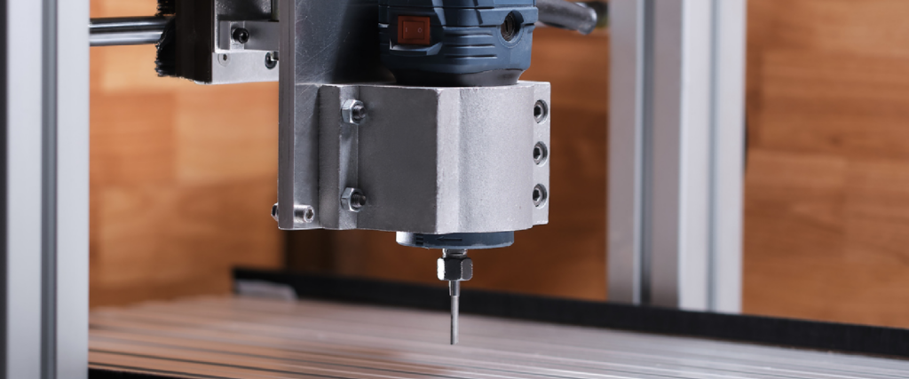
A CNC router is an automatic machine tool with a computer-controlled system. It’s used for milling, drilling, engraving, cutting, and, of course, routing. A CNC router primarily cuts wood but can be used for lighter materials, including foam, plastics, acrylic, glass, copper, brass, aluminum, PVC, and MDF. Similar to a milling machine, it can produce precise and complex shapes with various router bits moving along three axes—X (front to back), Y (left to right), and Z-axis (up and down).
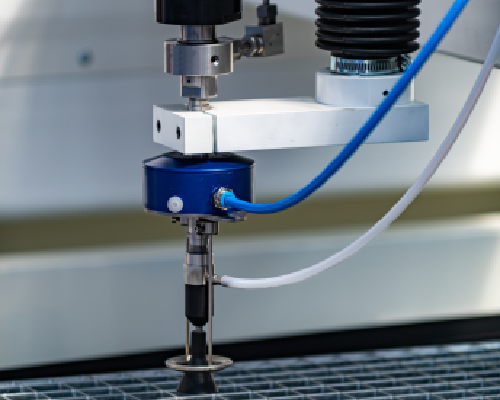
As the cutting tool carves and shapes the workpiece, the router produces dust and small particles. Helped features like a dust collector play a crucial role in capturing this debris, ensuring both the cleanliness of the work area and the longevity of the machine. This feature not only preserves the machine’s accuracy but also enhances the overall safety and health conditions of the workspace, making it a vital part of the CNC routing process.
Routers vs Other Machines
CNC routing is often used for woodworking and CNC mills for metalworking. Gantry-style CNC routers are usually less robust than their CNC mill counterparts because the mills are almost always made of heavy-duty cast iron or steel construction. In contrast, the routers might have an aluminum, plastic, or plywood framework.
Compared to CNC plasma cutters and laser cutters, routers are really versatile when it comes to handling different materials. While plasma and laser cutters are great for metals, routers can easily work with a variety of materials like wood, plastics, foams, and even some softer metals. This makes routers a go-to choice for projects that need detailed work and a nice finish, like crafting signs, woodworking, or artistic designs. Routers use actual cutting tools that give you more control over depth and let you carve in 3D, something plasma or laser cutters can’t do. But remember, while routers are great for their versatility and detail, they might not be as fast or as good at cutting through really tough materials as plasma or laser cutters.
Common Uses
Like CNC milling, CNC routing offers versatility and repeatability, meaning you can use it for numerous applications. They are most commonly used for woodworking due to their exceptional precision and ability to handle intricate designs and cuts, making them ideal for creating detailed wood projects. They can work on a range of wood types, from softwoods to hardwoods, and they can perform a variety of tasks like carving, engraving, and shaping.
CNC routers are used for furniture crafting, prototyping, parts creation, and other common tasks. Here are a few of them:
Cabinets and Components
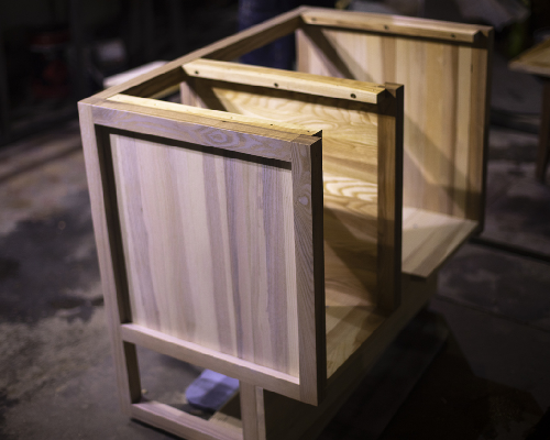 CNC routers are ideal for CNC woodworking projects making them the perfect choice for cabinet doors, drawer fronts, and boxes. Although the possible designs are infinite, each component must be uniform from piece to piece, and CNC machining ensures they are.
Furniture Making
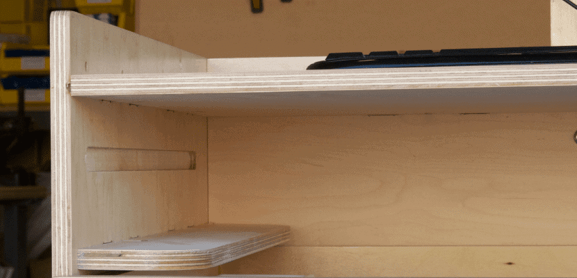 The furniture industry has the potential for mass-producing wooden products, and because of that, the CNC router machine is the perfect fit for creating intricate designs quickly and accurately. More and more hobbyists make money with CNC furniture every year.
Rapid Prototyping
 No more hand-carved prototypes or waiting for custom-milled parts from a vendor since CNC routers have arrived on the scene. Making design changes is as easy as editing a program, so you can quickly have a working prototype for testing and analysis.
Engraving
 Engraving is a common task for CNC routers. They provide the details and accuracy you require with engraved items. Many CNC routers even include a laser engraving kit to make the engraving process much faster.
Sign Making
 Making signs is time-consuming, so businesses are turning to the CNC router machine for these custom products. Many companies are creating their logos in formats that can be converted to a CNC router’s format.
Musical Instruments
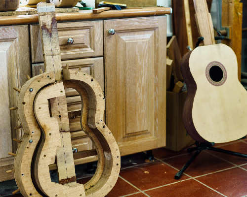 Musical instruments are now being created on CNC routers with impressive results. The inlays, fretwork, and body and neck carvings are all produced with precision and speed.
Other applications include mold making, handicrafts, and medical, aerospace, military, and transportation parts.
The great thing about a CNC router machine is you can use it out-of-the-box for projects that you can sell.
Important CNC Router Features
Whether you’re looking for tips on choosing a CNC router to add to your business or home workshop, there are specific things you’ll need to keep in mind as you research. Here are the most relevant considerations:
Drive System
 Your drive system moves your CNC router’s axes. It’s comprised of the motor, ball screw, lead screw, or rack and pinions, working together to transfer controlled linear motion. CNC machines offer a choice of three types of drive systems:
- Rack and Pinions work best on longer axes and are less costly. The meshing of the two gear-like components moves the machine tool.
- Lead Screws are typically more accurate than the rack and pinion but don’t work as well as ball screws. They do work well for vertical applications (Z-axis).
- Ball screws are the most expensive of the drive systems but will machine your parts with greater accuracy and efficiency.
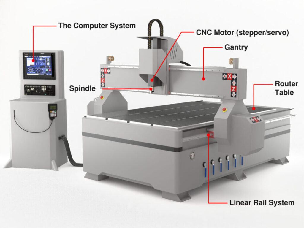
Motor System
You will find two main motor systems in most CNC router machines: the stepper motor system or the servo motor system.
- Stepper motor systems are sometimes referred to as open-loop control motors. Stepper motors rotate (step) from one position to another, are less expensive, and are better for low-to-medium-speed applications.
- Servo motor systems are often called closed-loop systems, are more expensive than steppers, but work well in high-speed, high-torque applications.
CNC Router’s Weight
Heavier machines generally provide heavy-duty performance, less vibration, and accurate machining. However, think about a desktop CNC router if you plan to transport your CNC machine frequently. Keep in mind that lightweight benchtop models have a smaller working area that restricts the type of work you can do.
Electrical Requirements
Determine the electrical capabilities of your shop since some routers are designed to work only with specific voltages. Make sure you have three-phase power, or you’ll need to install it if you buy a more sophisticated model. If you want a desktop model, it most likely will come with single-phase power and work in your home shop.
Software Requirements
Consider the software requirements of the CNC router. You might want to choose a software package specific to your business, such as software for cabinet making or engraving.
Budget
Your budget is a critical factor when searching for a CNC router. Depending on whether you want the machine tool for a small business, a large shop, or to pursue a hobby, prices will vary substantially. Also, include the cost of accessories, such as collets and router bits, in your estimation.
Brand
There are dozens of companies to choose from when buying a CNC router machine. While the considerations above are most important, many amateur hobbyists or home machinists start their journey on Amazon.
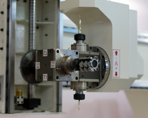
Accessories
If you’re buying a new router, check to see what accessories it comes with and which ones you’ll need to buy. Accessories like automatic tools changers, end mills, dust collection units, vacuum systems, computers, and software upgrades may not be included with your CNC router machine and can add additional costs new buyers should be aware of.
Your Uses
Before you spend tens of thousands on a machine, consider your likeliest uses. If you’re a machinist, the smaller less heavy-duty CNC routers likely won’t hold up to the everyday demands of a shop. If you’re interested in starting a woodworking business, do you need to upgrade to a machine with more power than smaller desktop routers? For the skilled amateur, you might consider building your own router or buying a cheap used one to see how you like it.
Building a CNC Router
If you didn’t realize it, you could make your own CNC router with the help of kits, plans, and tutorials. The machines can be fabricated from materials ranging from particle board to metal. Because they have relatively loose tolerances compared to a milling machine or lathe, it’s possible to turn building one into a DIY project.
However, the question of whether you can build a CNC router or whether you should build it is one we get asked a lot at CNC Masters. Here are the factors you should consider:
The advantages of building a CNC router include:
- You can choose a CNC router kit that meets your requirements without buying features you don’t need.
- You will save money.
- You should get a strong sense of satisfaction and accomplishment.
The disadvantages of building a CNC are:
- You will invest a lot of time and effort in selecting, purchasing, and assembling the CNC kits you will need.
- Assembling the CNC router kits or CNC router components requires technical knowledge and skills.
- The DIY CNC router might only be available in a small size with basic functions that do not meet your needs.
Is it cheaper to build or buy a CNC router?
Most CNC wood routers cost tens of thousands of dollars upfront. The most basic three-axis routers sell for between $5,000 and $10,000, while mid-range machines are likely to cost anywhere from $25,000 to $50,000. When you get to the full-scale CNC routers, they start at $50,000 and go up from there.
It is far cheaper to build your own CNC router. You can find DIY kits at popular online stores. As mentioned above, building a CNC router will take significant time and knowledge of CNC routers, and it’s important to choose a router kit that will meet your needs.
When you buy a complete CNC router, there are several advantages. Firstly, you get a machine capable of heavy-duty, long-term, and high-intensity work, which is essential for robust and continuous operation. Additionally, purchasing from a CNC machine tool manufacturer means you have expert support to answer any queries you might have, along with a warranty that protects your investment. There’s also the added benefit that if the machine is made in the USA, you can expect reliable after-sales service to swiftly address any issues that arise.
On the flip side, buying a complete CNC router also comes with its disadvantages. One of the most significant is the cost, which is likely to be higher than if you were to buy a CNC router kit. Moreover, if your purchase is from a foreign CNC machine tool manufacturer, be prepared to incur additional freight and customs fees. And let’s not forget the time and effort required to find a reliable manufacturer, a crucial step to ensure you’re getting a quality product that meets your needs.
Should you buy a CNC router?
If you’re a skilled machinist, you know very well the necessity of owning a great CNC router machine. However, if you’re looking to take your DIY small shop projects to the next level and maybe even start your own machining or woodworking business, here are some of the best reasons we know to buy your own CNC router:
- Precision: CNC routers are machines controlled by computers that can make detailed designs with great accuracy. This is hard to do with manual hand tools or non-CNC machines, so CNC routers are perfect for creating complicated shapes and patterns.
- Productivity: CNC routers work both non-stop and automatically, so they’re faster and more efficient than hand tools. This helps businesses make more products faster, leading to higher profits.
- Versatility: CNC routers can work with many materials, like wood, plastic, metal, and foam. You can make custom designs for different industries, like furniture, signs, cars, and airplanes. A CNC router can be programmed to make new designs or change existing ones with ease.


