CALL US TODAY

CALL US TODAY

this is a waterjet cutting machine

Waterjet Machine Guide: Types, Uses, Price, Features

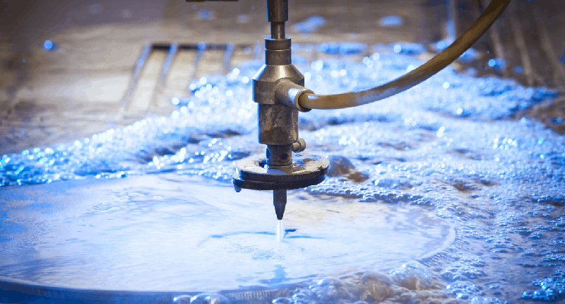
A waterjet machine is a versatile addition to any manufacturing shop, allowing for precise cutting across a range of materials and thicknesses. This machine operates by propelling water at high velocity and pressure, effectively eroding the material it cuts, akin to machining but without the need for cutting tools. Itā€™s an industrial powerhouse capable of slicing through metals, plastics, composites, ceramics, and even harder materials. For softer materials like wood and rubber, pure water suffices, while tougher materials require an abrasive additive, such as garnet or aluminum oxide, to enhance cutting power.

The process usually occurs underwater to reduce noise and mess, with the water jet exerting a force of over 60,000 PSIā€”thirty times stronger than a standard power washer. This high-pressure waterjet stream is channeled through a tiny nozzle, measuring between 0.010ā€ and 0.015ā€ in diameter. The waterjet system includes a pump and a critical filtering component. Only clean water can achieve the necessary pressure for consistent cutting, protecting the machineā€™s sensitive high-pressure parts from damage by impurities and minerals.

Waterjet cutting has become a powerful and popular tool used in many manufacturing processes around the world. Read on to find out why.


diagram of a cnc waterjet cutting machine

What are the components of a CNC waterjet?

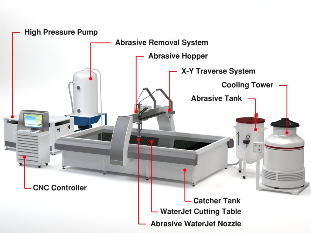
Three primary components are required to produce the high-pressure stream of water resulting in an accurate cutting edge.

The High-Pressure Water System

This system includes the pump that generates the pressurized water and all the plumbing needed to deliver it.

The Machine

The multi-axis waterjet (X, Y, Z axes) machine includes the cutting head, waterjet table, abrasive cutting nozzle, and material support catcher.

The Control System

Software in the high-performance control system manages the operator interface, X, Y, Z-axis motion control, nozzle positioning, and a velocity feedback system.

cnc waterjet cutting sheet

How Does a Waterjet Work?

The waterjet cutting process is versatile and can be accomplished in various ways. Most methods include an abrasive added into the water to help cut particles from the workpiece into a shape meeting precise specifications. Here is how the waterjet process works:

Determining Kerf Width

Kerf width refers to the material removed during the CNC waterjet process, typically 0.040 inches wide or less. The kerf size is a critical design factor and must be accounted for when determining the dimensions of the final product. The dimensions of the final part will only be accurate if the kerf is taken into consideration upfront.

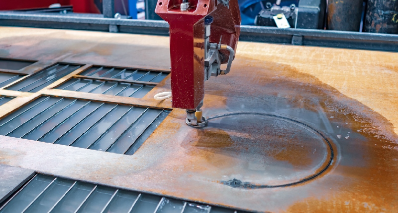
Initial Waterjet Piercing

Piercing is another name for the first cut the waterjet cutter makes, and it starts the water jet cutting process, much like a plunge cut might initiate the beginning of a lathe process. The most common methods of piercing include stationary, linear, circular, and low pressure, depending on the material and the least amount of scrap produced.

Pressurizing the Water

The most often used method of pressurizing the water is a linear intensifier. Linear intensifier pumps use pressurized hydraulic oil at a pressure of 3000 psi. The low-pressure oil pushes against a piston with a face area twenty times larger than the high-pressure plunger that pushes against the water. Because the low-pressure pump is twenty times larger than the high-pressure pump, the pressure on the larger plunger is intensified twenty-fold, producing a water pressure of 60,000 psi.

Traveling Through the Tubing

The pressurized water moves through high-pressure tubing to the cutting head. The tubing is made from thermoplastic or stainless steel and has exceptional tensile strength, yield, and a smooth interior surface.

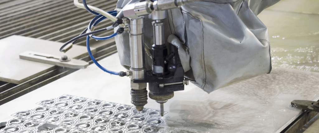
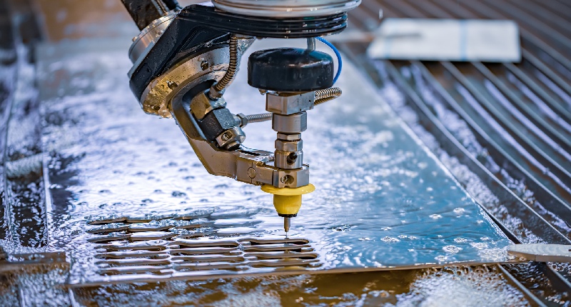
Waterjet Cutting Head

The pressurized water and garnet exit the cutting headā€™s orifice at nearly four times the speed of sound and can cut steel over one foot thick. As the water passes through the orifice of the cutting head, made of diamond, ruby, or sapphire with a .010ā€ to .015ā€ hole, its velocity increases to over 90,000 psi, directly affecting the waterjet cutting process.

Pure Waterjet Cutters vs. an Abrasive Waterjet Cutting System

Pure water jet cutters are the original water-only water jet cutting tool. Pure waterjet cuts soft materials like foam, plastic, paper, insulation, cement board, and automotive interiors. They produce a thin stream that provides excellent details with little wasted material.

An abrasive waterjet machine is much like a pure waterjet, except garnet abrasive material is pulled into the head and mixed at high speed with the water. The resulting abrasive waterjet stream is one thousand times more potent than the pure water cutter, allowing it to cut hard materials like metal, ceramic, stone, glass, and composite.

abrasive water jet machine
An abrasive water jet machine cutting an aluminum plate

Other Styles of Waterjet Machines

There are other types of waterjet cutting machines, including 3D Printers, micro waterjets, and robotic waterjets. However, the style of any waterjet cutter is determined by its gantry design, which is the system that holds and supports the cutting head:

  • Cantilever Gantry Machines: These have one arm over the table holding the cutting tool. Theyā€™re easy to use but canā€™t handle big pieces of material.
  • Bridge Style Gantry Machines: These have a bar across the table, which the cutter moves along. Theyā€™re known for being stable and are good for cutting large things.
  • Flying Bridge Gantry Machines: Similar to bridge style, but the whole top part moves with the cutter. Theyā€™re used for very accurate cutting on big machines.
  • Articulated Arm Gantry Machines: These cutters have a bendable arm, like robot arms, to move the cutter. Theyā€™re best for detailed cuts or small spaces.

Waterjets vs Other Machine Tools

Waterjet cutting has several advantages over other cutting processes, such as laser cutting machines or plasma cutting. Waterjet systems provide better accuracy, can cut complex designs, and can handle thermally sensitive surfaces. The process does not heat the material or change its temper and leaves clean-cut edges that do not require secondary finishing.

How much does a CNC waterjet cost?

Abrasive waterjets are relatively new and have become candidates to replace traditional processes like drilling, profile milling, gear cutting, slitting, broaching, and sawing in various industries. The approximate price for a 2-axis abrasive system should be between $100,000 and $200,000, and a water-only CNC waterjet is usually in the $50,000 and $100,000 range.

cnc waterjet cutting machine

Types of Waterjet Cuts

In some ways, the waterjet cutting process resembles using a bandsaw to remove material. However, material cutting in todayā€™s manufacturing environment is more complicated than a band saw can handle. On the other hand, water jet cutting machines can perform many different cuts depending on the application.

The following list displays the versatile functionalities of the CNC waterjet:

One-Dimensional Cutting

One-dimensional waterjet moves are stationary cuts made through one pass of the workpiece. Mainly used for trimming, these cuts are the most basic maneuvers you will make in waterjet cutting, and you can perform them with or without an abrasive added to the water.

Two-dimensional (X and Y)

Two-dimensional cutting requires CNC control and programming. CNC machines have a servo motor to control positioning and cutting speed. The Z-axis controls the height of the cutting head and adapts to various material thicknesses. A water-filled catcher tank has slots to support the workpiece.

Three-dimensional (X, Y, and Z)

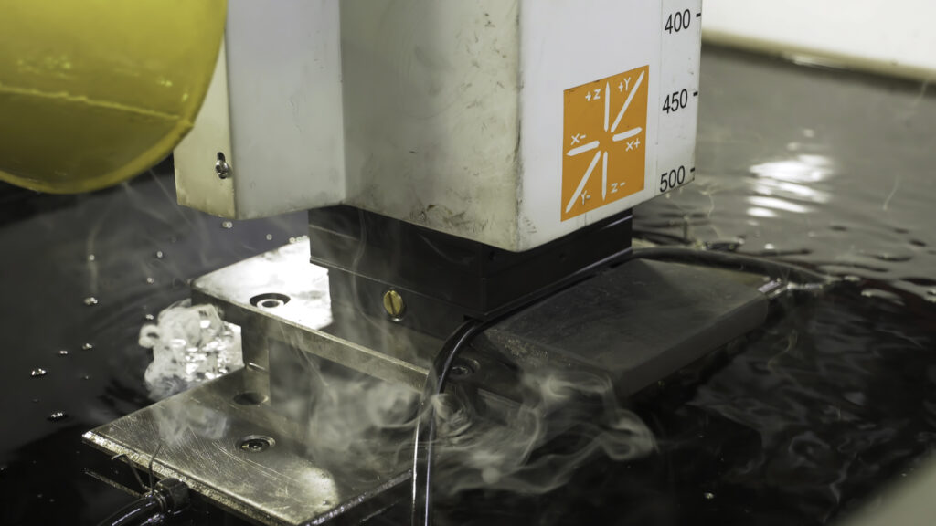
Three-axis cutting involves the X-axis (left to right), the Y-axis (front to back), and the Z-axis (up and down). The workpiece is always stationary as the cutting head moves along the three planes.

Four-dimensional (X, Y, Z, and A)

Using four-axis cutting, the workpiece is processed by the X, Y, and Z axes, with the addition of rotary motion. The A-axis the workpiece to be flipped for the waterjet to remove material from both sides of the workpiece or to cut holes in its side.

Five-Dimensional (X, Y, Z, A, and B)

A 5-axis waterjet system allows the workpiece to be moved along five axes simultaneously. The workpiece travels along the two-dimensional X, Y, and Z axes, with different rotational movements around those three axes, performing 180-degree rotations. Five-axis machines enable the fabrication of complex shapes and components but require a great deal of CNC programming.

cnc waterjet in machining shop

What are Some of the Applications for a CNC Waterjet?

The waterjet system has become a precise manufacturing process with quick turnaround times, making it the preferred cutting method for several industries, especially those requiring tight tolerances. Waterjet cutting has been gaining favor among several industries for many reasons. Here are some of them

Aerospace Industry

Aerospace components are often complex and require precision, and by their nature, they do not allow room for mistakes. It is one of the main reasons that waterjet cutting has become an essential part of manufacturing aerospace parts and components such as control panels and jet engine parts.

Abrasive waterjet is the choice for cutting the steel, brass, Inconel, and aluminum used in turbine blades, wing sections, brake components, and landing gear.

Auto Industry

Robotic systems are a mainstay of the automotive industry, and water jet cutting integrates well into automated systems. However, the auto industry applies both methods of water jet cutting, pure water jet cutting shapes interior carpets, insulation, and head linings, while producing minimal material waste.

Water jet cutting does not create heat-affected zones (HAZ), generate noxious fumes, or place stress on the workpiece. Instead, it produces burr-free surfaces that avoid the need for secondary finishing.

Medicine

In medicine, water jet cutting technology replaces traditional surgical cutting tools for specific operations. For example, high-pressure spiral water crushes and sucks liver parenchymal cells in treating tumors. It does not produce heat that could damage other organs, minimizing the possibility of bleeding. By altering the pressure and flow rate, it is now possible to dissect human tissue with less trauma, bleeding, and postoperative problems.

Glass

Cutting glass is a tricky process that requires precision tools to avoid puncturing or breaking the glass. Like the medical industry, cutting glass with a water jet allows for modifying and adjusting the water stream to avoid damaging the glass. The stream can cut any shape, form, configuration, or workpiece to the most minute detail. The accurate high-pressured water stream enables cutting holes and notches without concerns about distortions.

Electronics

Manufacturers are continuously looking for ways to reduce costs and increase efficiency. Cost is a significant issue in electronics production, and the efficiency of water jet cutting has made it an essential part of electronics production. CNC waterjet is excellent for cutting circuit boards or stripping wires without damaging them.

Fiberglass

Water jet cutting can shape and form fiberglass without producing dust or excessive waste. The rigidity of the fiberglass is usually not a factor since the waterjet cutting process works whether shaping insulation or creating boats.

What are the Advantages of CNC Waterjet Cutting?

cnc waterjet cutting materialsWaterjet cutting offers manufacturers versatility and flexibility like no other. The range of benefits associated with using waterjet cutting gives this technology its edge over others, such as laser and saw cutting.

No Heat-Affected Zones

What is a heat-affected zone? Itā€™s an area of metal that has not been melted but has undergone changes in properties due to exposure to relatively high temperatures. Cutting processes generating high heat created problems, such as hardened edges and distortion for workshops. Manufacturers have overcome these issues by using waterjet cutting, a cold-cutting process.

Accurate Internal Cut-Outs

The waterjet cutting process creates all sorts of custom patterns, unique designs, and logos. Cutting accuracy of Ā±0.0005ā€ is possible with a waterjet cutter, making it the tool of choice for precise internal cut-outs.

Excellent Edge Quality

Manufacturers achieve smooth, burr-free edges through a combination of the correct water speed, pressure, nozzle size, and flow rate. In most cases, waterjet cutting eliminates the necessity for secondary finishing, saving significant time and money while improving efficiency along the production line.

No Tool Changes

Waterjet cutting allows you to work on different materials without changing tools. Merely adjust your feed rate for the new material and thickness, and start the next cut.

Brings Down Costs in the Shop

Waterjet cutting is a cold-cutting process. Other heat-producing machining methods can create heat zones that often cause the parts to warp, making them out of tolerance and even unusable. With its cold-cutting process, the CNC waterjet minimizes or eliminates the chance of scrapping machined parts. And because waterjet-cut parts require little edge treatment or secondary finishing, you save money on those extra operations.

Material and Thickness Are Not Major Factors in Waterjet Cutting

The high-pressure cutting stream of water and the abrasive solution will cut through most materials. Also, material thickness will not be as essential because waterjet machines will cut aluminum, multi-layer materials, composites, and hardened steels in thicknesses over one inch.

Are There Disadvantages to CNC Waterjet Cutting?

Although the benefits of the CNC waterjet are significant, there are a few cons you should consider:

Longer Cutting Times

When compared to traditional manufacturing processes, such as CNC milling and lathe turning, CNC waterjet cutting is significantly slower.

Expensive Process

Hobbyists, DIYers, and smaller shops might find that CNC waterjet technology is out of their reach.

Difficult to Hold Dimensions on Thicker Materials

Waterjet cutting will likely be less effective on very thick materials and will pose issues in maintaining dimensional accuracy.

EDM Might Be a Better Option

Depending on the tolerances, type of metal, and intricate shapes, EDM could be a better choice than waterjet cutting.

About Peter Jacobs

Peter Jacobs is the Senior Director of Marketing at CNC Masters, a leading supplier of CNC mills, milling machines, and CNC lathes. He is actively involved in manufacturing processes and regularly contributes his insights for various blogs in CNC machining, 3D printing, rapid tooling, injection molding, metal casting, and manufacturing in general. You can connect with him on his LinkedIn.

Have Questions? Need a Quote?

Looking for more information about our CNC machines and services? Contact us today.

Contact

Slide 1

29. Create a Peck Drilling Program in Circular or Rectangular Patterns
Using the Circular or Rectangular Drilling Wizards, you can program the machine to drill an un-limited series of holes along the X and Y planes. Program it to drill straight through to your total depth, use a high-speed pecking cycle, or deep hole pecking cycle. You can program the cut-in depth and return point for a controlled peck drill application to maximize chip clearance.

Slide 1

20. Change up to 30 tools with compensation, and store your tool offsets for other programs
The MX supports…

Slide 1

21. Use the optional ATC rack up to 8 tools for milling, drilling, and rigid tapping applications
The CNC Masters Automatic Tool Changer Rack and Tools (US Patent 9,827,640B2) can be added to any CNC Masters Milling Machine built with the rigid tapping encoder option. The tutorial will guide you through the set-up procedure using the ATC tools.

Slide 1

22. Use the optional Rigid Tapping Wizard without the need for tapping head attachments
When you order your CNC Masters machine, have it built with the optional rigid tapping encoder. You can take any drill cycle program and replace the top line with a tapping code created by the wizard to tap your series of holes up to 1/2ā€ in diameter.

Slide 1

23. Use the optional Digital Probe to scan the profile and/or pockets of your fun/hobby type designs to write your tool path program and machine out a duplicate of your original design To ā€œsurfaceā€ scan an object, you can program the probe along the X or Y plane. The stylus will travel over the part starting on the left side front corner of the object and work its way to the end of the part on the right side. Depending on how the stylus moves, it will record linear and interpolated movements along the X, Y, and Z planes directly on the MX Editor.
To ā€œpocketā€ scan an object containing a closed pocket such as circles or squares, the scan will start from the top front, work its way inside of the pocket, and scan the entire perimeter of the pocket.
Under the Setup of the MX software you will find the Probe Tab which will allow you to calibrate and program your probe. Your ā€œProbe Stepā€, ā€œFeedā€, and ā€œData Filterā€ can also be changed on the fly while the probe is in the middle of scanning your object.

Slide 1

24. Use work offsets G54-G59 for nesting applications
The work offsets offer you a way to program up to six different machining locations. Itā€™s like having multiple 0.0 locations for different parts. This is very useful especially when using sub-routines/nesting applications.

Slide 1

25. Create a Rectangular Pocket / Slot with our selection of Wizards to help you build a tool path program
The Cycle Wizards for the mill or lathe makes it easy to create a simple tool path without needing to use a CAD and CAM software.
On this Wizard, the Rectangular Pocket / Slots, can be used to form a deep rectangular pocket into your material or machine a slot duplicating as many passes needed to its total depth.

Slide 1

26. Create a Circular Pocket Wizard
Input the total diameter, the step down, and total depth and the code will be generated.

Slide 1

27. Do Thread Milling using a single point cutter Wizard

Slide 1

28. Cut a gear out using the Cut Gear Wizard with the optional Fourth Axis

Slide 1

19. Disable the axis motors to manually hand crank each axis into place
Easily de-energize the axis motors by clicking [Disable Motors] to crank each axis by hand, and then press [Reset Control] to re-energize the axis motors.

Slide 1

30. The MX interface can easily be interchanged from Mill Mode to Lathe Mode
Use this interface for your CNC Masters Lathe. It contains all the same user-friendly features and functions that comes in Mill Mode. Simply go to the Setup page and change the interface.

Slide 1

31. Use Tool Change Compensation or the optional Auto Tool Changer Turret if your application requires more than one tool in a single program
You can offset the length and angle of each tool and record it under Tools in your Setup. The program will automatically pause the latheā€™s movement and spindle allowing you to change out your tool, or allowing the optional ATC Turret to quickly turn to its next tool and continue machining.
On the MX interface, you also have four Tool Position buttons. Select your desired T position, and the auto tool post will quickly turn and lock itself to that position.

Slide 1

32. Use the Lathe Wizard Threading Cycle to help you program your latheā€™s internal or external threads in inches or metric

Slide 1

33. Use the Lathe Wizard Turning / Boring Cycle to help you program simple turning and boring cycles without having to go through a CAM or writing a long program with multiple passes

Slide 1

34. Use the Lathe Wizard Peck Drilling Cycle to help you program your drill applications or for face grooving

Slide 1

35. Facing / Grooving / Part Off Cycle Wizards ā€“ with Constant Surface Speed
These cycles can be used with Constant Surface Speed allowing the spindle speed to increase automatically as the diameter of the part decreases giving your application a consistent workpiece finish. With CSS built into the wizard, there is no need to break down the cycle into multiple paths and multiple spindle speed changes.

Slide 1

36. This is our list of supported G and M codes which can be found under Tools > G Code/ M Code List in the MX
If you plan to use a third-party CAM software to generate your tool path program, use a generic FANUC post processor and edit it to match our list of codes. As an option, we also sell Visual mill/turn CAM software which comes with a guaranteed post processor for our machines to easily generate your tool path programs based on your CAD drawings.

Slide 1

37. Our pledge to you…

Slide 1

10. Run each tool path independently to study its movement
1. Run the machine on Trace mode. You can run each tool path independently, one line at a time to study the tool path movement on the machine to verify the position of the application and if any fixture/vise is in the way of the cutterā€™s path.

2. You can also verify your program by clicking on the Trace and Draw buttons together. This will allow you to view each tool path independently one line at a time in the Draw Window.

Slide 1

2. Clutter Free Interface
The MX is engineered for the CNC MASTERS machine so you do not have to fiddle with a detailed complicated configuration that can be overwhelming. Just load in the MX and start machining!2. Clutter Free Interface
The MX is engineered for the CNC MASTERS machine so you do not have to fiddle with a detailed complicated configuration that can be overwhelming. Just load in the MX and start machining!

Slide 1

3. Features Tour and Tutorials Included
The Features Tour will give you a quick run-down on all the features the MX can do for you. The Tutorials are easy to follow even for the first time CNC machinist.
Feel free to download the MX on any of your computers. We recommend downloading the MX along with your CAD and CAM software there at the comfort of your office computer to generate your tool path programs. You donā€™t need to be hooked up to the machine either to test your program in simulation mode.

Slide 1

4. Navigate and Edit Your Program through the MX interface with Ease
With a few clicks of the mouse or using touch screen technology, you can easily navigate through the MX interface importing saved programs into the Editor from the File drop down menu. Using standard windows features to edit your program you can then lock the Editor Screen to avoid accidental editing, and if you need to insert a line in the middle of a program, just click on [ReNum] to re-number your tool path list.
You can create a program or import CAM generated G-code tool paths into the Editor
The X Y and Z W arrow jog buttons are displayed from the point of view of the cutter to avoid confusion when the table and saddle are moving. You can also adjust your spindle speed and coolant control while jogging each axis.

Slide 1

5. Feed Hold ā€“ Pause in the Middle of your Program
Feed Hold lets you pause in the middle of a program. From there you can step through your program one line at time while opting to shut the spindle off and then resume your program.
You can also write PAUSE in the middle of your program and jog each axis independently while your program is in pause mode.

Slide 1

6. Hot Keys
Hot Keys is an alternative method to easily control your machine using your hard or touch screen keyboard. One can press P to pause a program, press S to turn Spindle On, G to run a program, Space Bar to Stop, J to record your individual movements one line at a time to create a program in teach mode.

Slide 1

7. Pick Menu ā€“ for conversational mode programming
Write FANUC style G-codes directly into the Editor or select commands off the [Pick] menu and write your tool path program in conversational mode such as what is written in the Editor box. You can even mix between conversation commands and G-codes in the same program.

Slide 1

8. Pick Menu List of Options
Use commands such as MOVE, SPINDLE ON/OFF, COOLANT ON/OFF, PAUSE, DELAY, GO HOMEā€¦. to write your tool path programs in conversational mode.

Slide 1

9. Draw the Tool Path to verify it before pressing Go
Hit Draw to view your tool path program drawing, check out its run time, or even simulate the tool path in 3D mode. This can be helpful to quickly verify your program before running it. You can also slow down or speed up the drawing or simulation process.
You can also hit Go within the Draw Window itself to verify the cutterā€™s position on the machine. The current tool path will be highlighted and simultaneously draw out the next path so you can verify what the cutter will be doing next on the program.

Slide 1

MX Software ā€“ Easy to Use, Easy to Learn ā€“ Included with your machine purchase
The MX software is designed to work seamlessly with your CNC Masters machine. It is made to work with Windows PC ā€“ desktop, laptop, or an all in one ā€“ on standard USB. Use it on Windows 8 or 10 64-bit operating systems.
No internal conversion printer/serial port to USB software or additional conversion hardware is used with the MX.

Slide 1

11. Counters display in Inches or Millimeters ā€“ Continuous Feed
1. When running a program, the counters will display a ā€œreal-timeā€ readout while the machine is in CNC operation without counting ahead of the movement.
2. The current tool path is highlighted while the machine is in operation without causing slight interruptions/pauses as the software feeds the tool path to the machine. The MX internally interprets a program ten lines ahead to allow for ā€œcontinuous machiningā€ avoiding slight interruptions as the machine waits for its next tool path command.
3. ā€œRun Timeā€ tells you how long it takes to run your tool path program.

Slide 1

12. Use the ā€œGo From Lineā€ command to start in the middle of your program
If you ever need to begin your program from somewhere in the middle of it, use [Go From Line] which you can find under Tools. The Help guide will walk you through how to position the cutter without losing its position on the machine.

Slide 1

13. Exact Motion Distance without over-stepping on an axis while jogging
Use ā€œRelative ONā€ to enter a specific coordinate to jog any of your axes to an exact location without having to write a program. Itā€™s like using ā€œpower feedā€ but easier. You can jog an exact distance on any of the axes without needing to keep the key pressed down and mistakenly over-step the movement releasing your finger too slowly off the jog button.
Letā€™s say you need to drill a hole exactly 0.525ā€ using the Z. So you enter 0.525 in the Z box. Next, adjust the JOG FEED RATE slider for the desired feed rate. Then ā€œclick onceā€ on the +Z or -Z button to activate the travel. In this case you click once the -Z button first to drill the hole exactly 0.525ā€. Then click once on the +Z button to drive the axis back up 0.525ā€.

Slide 1

14. Teach Mode ā€“ Jog Input
You can create a tool path program by storing each point-to-point movement by simply jogging an axis one at a time. Click on either of the Jog Input buttons to store each movement on the Editor Screen. You can then add Spindle ON, feed commands, and press GO to run the new program as needed. This is a great feature to help you learn to create a program by the movements you make on the machine without necessarily writing out an entire program first.

Slide 1

15. Override on the fly to adjust the Jog Feed to Rapid or the Spindle Speed during the middle of a program
1. Jog Feed and Rapid with Override: You can adjust feeds using the slider from slow minimum 0.1ā€³ per minute to a rapid of 100ā€³ per minute of travel. You can even micro-step your jog as low as 0.01ā€/min. The [-][+] buttons allow you to fine tune feeds in 5% increments while the program is in motion.
2. Spindle Speed with Override: You can adjust speeds using the slider from a slow minimum RPM to the max RPM according to the machine setup. The [-][+] buttons allow you to fine tune feeds in 5% increments while the program is in motion.

Slide 1

16. Adjust Counters using Pre-Set if you cannot begin the program from 0.00
In a situation where you cannot begin your cutter at itā€™s 0.00 location, you can ā€œPre-Setā€ directly into the counters by typing in your beginning coordinate. You can press Go from here to run your program. You can also ā€œzero allā€ or ā€œzeroā€ your counters independently. With one click of the [Return to 0.0] button, all axes will travel back to its respective 0.0 on the machine.

Slide 1

17. Set and Save your 0.00 position for future runs
Set and save your 0.00 position on the machine. These coordinates will be recorded as the first line of the program in the Editor Screen. Should you desire to return to this program at a later date, you only have to click on the Set Zero Return button. This will command the machine to automatically jog each axis to its saved ā€œsetā€ 0.00 position according to the recorded coordinates at the first line of the program.

Slide 1

18. Create a ā€œHomeā€ position to clear your application and run multiple times
Letā€™s say you need to machine one application times 100 pieces. This usually requires a jig to retain that physical 0.00 position. But in this case, you want the program to end with a clearance of the axes to easily switch out the next piece of stock and start again. With Save Home, you have the ability to save this offset (home) position while still retaining your Set Zero position where the machine will mill your part out. Pressing [Save Home] will record this new position under the Set Zero line in your program.
Pressing [Go Home] will jog your axes back to your ā€œsaved homeā€ position where you originally pressed the Save Home command. You can also input GO_HOME from the Pick Menu as its own tool path in your program. At the completion of your program the axes will end at your Home position. Replace your part, then press [Return to 0.0] button to allow the axes to return to its zero position, and press Go to start your next run.

previous arrow
next arrow