You already have a few CNC machines in your metalworking shop, and now you want to venture beyond the milling machine, lathes, and routers and purchase a CNC plasma cutting system. It’s a relatively significant decision since a CNC plasma cutter requires a substantial up-front investment.
You might be convinced that a plasma cutter will pay off over time by saving you money on outsourcing your profile metal cutting work with the speed and efficiency of a plasma system. However, it can be intimidating for any first-time buyer to consider the many factors in selecting a suitable plasma cutter for your business or home workshop. Remember, purchasing a plasma cutter is a lot like buying a welder: you choose one according to your work.
This guide will introduce you to the CNC plasma cutting table and some of the primary factors you should consider before purchasing one. But first, here is some background on the plasma cutter table.
What Is a CNC Plasma Table?
The CNC plasma cutting table is one of the most efficient and versatile tools for steel plates and pipe cutting, even on thicker materials. The tables come in various sizes, so you’ll need to base your table purchase on the manufacturing and construction applications you plan to do. CNC plasma cutting tables have moving parts, including a gantry for traversing the X and Y-axis and a plasma torch carriage for the Z-axis (up and down).
Plasma cutting machines are computer automated, allowing for the highest quality cuts, meaning the design software for your CNC plasma cutting table is another critical component. To ensure accuracy, CAD (computer-assisted drawing) enables designers to draw the part digitally before taking the initial cut.
CNC plasma tables typically come with tech support, a toll-free number for assistance, and a one or two-year warranty on labor and parts.
What Is The Difference Between a Plasma Table and a Plasma Cutter?
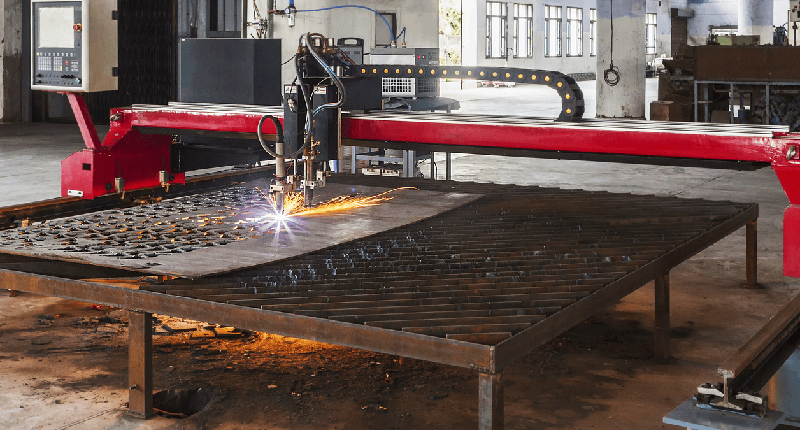
A plasma torch is a device that cuts through electrically conductive materials by using an accelerated jet of hot plasma directed at the material. The plasma table carries this plasma cutter, which has a flat surface of steel slats spaced approximately 2” to 4” apart. The slats support the workpiece and absorb the heat from the thermal cutting process.
The plasma torch is suspended directly above, rides on a bridge, officially called a gantry, and moves as CAD/CAM software directs. As opposed to hand-held plasma cutters, CNC plasma cutting tables slice through metals at speeds up to 500 inches per minute, resulting in high-quality cuts in a fraction of the time.
The plasma torch and power supply provide the cutting capacity and quality, while the machine’s design is responsible for accurate parts. As such, a combination of a durable machine design and power source will produce the ideal results.
What Features Should I Look For in a CNC Plasma Table?
CNC plasma cutters vaporize metals into a powder form and remove them from the cut zone using a high stream of air or gasses. They all require a plasma gas and an assist gas to work correctly, and the machines vary in size, price, and functionality.
As you shop for a CNC plasma cutting machine, look for the following features:
1. User-Friendly CNC Control
Most entry-level machines are operated from a personal computer instead of a sophisticated control unit. A computer might not be sufficient in a high-production environment but typically is adequate for a small shop. This method helps control the costs for hobbyists, the one-person shop, and smaller fab shops without high production demands. If you require extra features, look for a CNC plasma table with an onboard diagnosis system for trouble-free maintenance.
2. Affordability
Many brands can deliver excellent motion control and precision, but they exceed the budgets of small shops, hobbyists, and beginners. However, a few brands offer industrial capabilities at an entry-level CNC plasma table price. Also, look for companies that offer flexible payment options and financing so you don’t struggle with a substantial lump-sum payment. You can save money upfront by delaying expensive add-ons for a later date.
You can save on driver motors, gearing, and electronics on plasma cutters not purchased for heavy use. Many entry-level plasma cutters come with stepper motors instead of servo drives, offering significant savings and equal reliability.
Remember, heavy-duty machines withstand the stress of constant use and provide a wider cut thickness, better cut quality, and faster cutting speeds. However, the mechanical components of a light-duty plasma cutter, sometimes called a DIY CNC plasma cutter, will be lighter, smaller, and have a lower price tag, which is ideal if you anticipate using something other than the machine for round-the-clock production.
3. CAD/CAM Software
CAD (computer-aided drawing) lets you draw your part digitally and input it into the CAM (computer-aided machining) software.
The CAM software applies correct tolerances, kerf width, lead-ins, and lead-outs using post-processing. The CAM file is entered into the CNC control, which converts it into signals that control the cutting process.
Some entry-level plasma cutters include combined CAD/CAM software, making the transfer from drawing to cutting the part quick and simple. It allows smaller shops to draw and trim pieces on the shop floor while they are at the machine.
4. Torch Height Control
Some plasma tables do not offer torch height control, reducing the overall cost of the plasma cutting system. However, height control is essential to edge angularity and the table’s longevity, and a plasma torch with torch height control (THC) will raise or lower it depending on how close it is to the metal.
5. Table Size
Tables range from 2’ x 2’ up to 5’ x 10’ and everything in between. Hobbyists and small fabrication shops can choose a smaller table and get started for around $1,000. Still, if you have industrial requirements, your CNC plasma cutter could cost $50,000 with a correspondingly larger table.
6. Output Power
As mentioned, the output power of a CNC plasma cutter determines what it can cut. For example, getting 12 amps of output power from a 120V machine means you can cut most 1/8” thick metal, while 60 amps from a 230V machine can cut most metals that are 7/8” thick. Some inverter-based plasma cutters provide high cutting output power but weigh far less than regular cutting machines offering that same cutting capacity.
7. A Fume Control System
All plasma cutters produce hazardous fumes and smoke, so you should seriously consider a method for extracting them. There are two primary ways to do this, and the water table is the more common since it’s found predominantly on entry-level CNC plasma cutters. The design is more straightforward, and the ongoing costs are reasonable. However, when you retire the machine, the water must be disposed of by regulations.
The downdraft fume extraction tables with large-capacity filter units are more efficient for production machines. A fan or blower pulls the smoke below the cutting bed slats in the downdraft system. The fume extraction filter removes fume and dust via ductwork built into the cutting table. This method is a safer, more ecological, albeit more expensive, method of extracting dust and fumes.
What Can I Make With a CNC Plasma Table?
CNC plasma tables are found in fabrication shops, automotive repair shops, industrial structural steel facilities, and construction companies. Some of their applications include:
- Cutting large beams on the construction site
- Scrapping operations at salvage dealers
- Metal sheets at fabrication shops
- Cutting into safes and vaults after customers are locked out
- Creating works of art
- Bevel cuts, precise holes, and unique shapes in industrial parts and components
Who Makes The Best CNC Plasma Tables?
There are several excellent brands of CNC plasma cutters from which to choose: the following three should be part of your shopping list:
1. STV Motorsports CNC Plasma Table Spar (X4400-4×4)
The STV Motorsports CNC plasma table is among the top-rated plasma cutters based on its versatility, reliability, and accuracy. It includes a water table to reduce the chances of the metal warping capture dust particles that could be hazardous to the operator.
Other features include:
- Cutting speed of up to 600 inches per minute
- Handle up to three-quarters of an inch thick steel plate
- Replaceable table slats
- Dry or water pan options
- Automatic torch height control
2. STV Motorsports SparX510 5×10 CNC Plasma Cutting Table
Like the STV Motorsport X4400-4×4, the SparX510 has an advanced cable management system, a water table, and an automated torch height control system. It also has stepper motors known for their accuracy and speed. The plasma cutter is designed to handle 3/4″ thick steel, copper, or aluminum plates, although it sacrifices cut rate on the thickest material.
Other features of this STV model:
- Study and durable parts made in the USA
- Lifetime technical customer support
- Cutting speed of up to 600 inches per minute
- Z-axis maximum 6” travel depth
- Highly accurate with a deviation of 0.002 inches per 12 inches
- Replaceable table surfaces
- Selectable input power of 110V and 220V
3. 5×10 Hypertherm Plasma Cutter Table for Sheet Metal & Tube
The 5×10 Hypertherm plasma cutter table with CNC controller is designed to cut sheet metals and metal pipes with a 4th rotary axis. Here are some of its other features:
- Model: STP1530R
- Table Size 1500x3000mm (5×10)
- Max Cutting Thickness: 40mm
- Pipe Cutting Size Diameter from 200mm to 600mm, Length up to 3000mm or 6000mm
- Plasma Cutting Speed 0-6500mm/min
- Stepper Motor
- Machine Frame: Welded Structure
- Machine Structure: Rack and Pinion Drive
Final Thoughts
CNC plasma tables provide precision, efficiency, and versatility to hobbyists, fabrication shops, and large industrial manufacturers, helping them to achieve impressive results. Anyone looking to purchase one should consider the above features and their situation (budget and work type) and buy a machine that meets their needs. If nothing seems to fit, numerous other CNC machines will!


