CALL US TODAY

CALL US TODAY

metal cnc lathe machine

The Beginner’s Guide to Lathe Machines

Even if you’re not intimately familiar with manufacturing and machining, you’ve probably heard of a metal lathe. These machines are quite common in machine shops, second only to milling machines in terms of popularity.

You might know what lathes are but understanding them is crucial, especially if you’re a business owner, plant manager, or supervisor in charge of purchasing one.

We’ll begin with the basics, helping you understand these versatile and essential machines. Then, we’ll move on to some helpful buying tips to make sure you’re ready and well-informed about your purchase.

cnc lathe diagram
A modern CNC lathe machine diagram, courtesy of CNC Masters

Check the CNC Masters Lathe that can run in CNC Mode and Manual Mode! Click here >>>

Lathe Machine Basics

Although most of us connect the lathe directly to the Industrial Revolution of the mid-18th century, you might be surprised to know that a lathe is an ancient tool, with evidence of its existence dating back to Ancient Egypt around 1300 BCE. Greek woodworkers around this same period also used lathes.

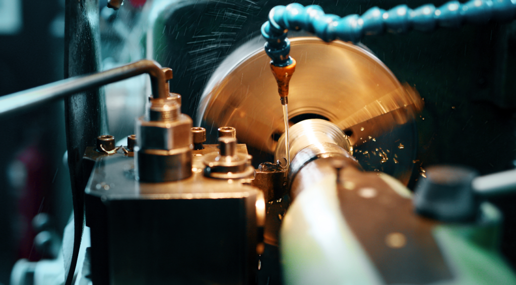
The lathe has been a machine tool for turning operations, creating cylindrical shapes like spheres and cones. Today, lathe machines are an essential part of most machine shops since lathe work is usually an integral part of the machining process. Recently, the CNC lathe machine, a precision machine tool machinists employ for various woodturning and metalworking projects, has become the go-to lathe for machining high-volume components that require accuracy and repeatability and the most complex projects.

Whether you are shopping for a manual engine lathe or power lathe, a mini-lathe that fits on your workbench, or a multi-axis CNC lathe for large-scale projects, you’re making a substantial investment, and there are things you should know before your purchase.

What is a lathe machine used for?

a lathe machine turning woodLathe functions typically fall into two categories: industrial and artisan machine tools. Industrial uses could include a small machine shop making replacement parts for old cars or farm equipment to large corporations producing everything from heavy machinery to aerospace components.

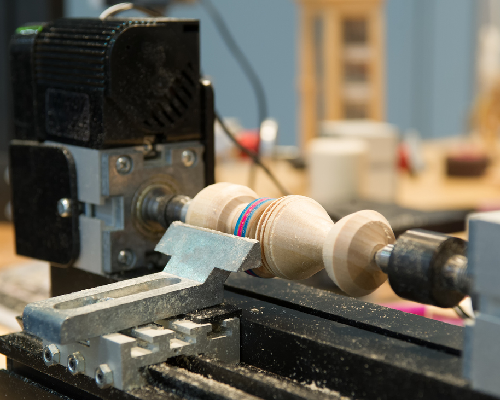
On the artisan end of the spectrum, craftsmen use lathes to create unique pieces from various materials, including sheet metal, wood, plastic, glass, epoxy, etc. For example, skilled wood lathe operators can transform a rectangular block into a chair or table legs. At the same time, an experienced machinist can turn the inside diameter of a rifle barrel, maintaining tight tolerances.

CNC metalworking lathes have multiple tool holders, allowing numerous operations to be processed on one setup without further human involvement. Even traditional engine lathes have access to quick-change tooling systems that significantly reduce set-up and tool-changing times.

Toolroom lathes are smaller, more accurate machine tools on the industrial side. As the name suggests, they are often found in a shop’s toolroom with other accessories like a tool grinder. A toolroom lathe is a lathe optimized for tool-and-die work and other precision parts with features not found on less expensive lathes, such as a collet closer and taper attachment.

What are the different types of lathes?

A small mini lathe machine

Although lathes can fit into several categories, there are three basic types of lathe machines: the traditional engine lathe, the computer numerical control (CNC) lathe, and the mini-lathe, or benchtop, often sold at distributors such as Amazon. You may find all three types in a modern machine shop, but there’s little doubt that the CNC lathe has become an indispensable machine tool because of its high-speed turning capabilities and high precision.

Machinists use CNC lathe machines to complete various metalworking projects, usually those high-volume components that require accuracy and repeatability. In contrast, traditional engine lathes have been mostly relegated to short runs, repair work, and secondary operations. Mini-lathes have become the favorites of hobbyists and smaller operations where space is at a premium.

Lathe Machine vs Mill

CNC Supra Milling Machine
CNC Milling Machine

Today’s multi-axis CNC machining centers can blur the lines between CNC lathes and CNC milling machines, but they are two separate and distinct machines for most practical considerations.

If you walk into most machine shops and other manufacturers, you will see lathes and milling machines on their shop floors. Although each machine follows the same machining principle of removing material from a block of material, how they shape the part differentiates between them.

The primary difference between a lathe and a milling machine is the relationship of the workpiece to the cutting tool. On a lathe, the workpiece spins about its axis, and the cutting tool does not rotate. The process is called “turning,” resulting in a cylindrical-shaped part. Operations performed on a lathe include turning, boring, ID/OD grooving, threading, drilling, and parting.

On the other hand, the milling machine’s cutting tool rotates about its axis while the workpiece remains fixed. This setup allows the tool to approach the workpiece from various directions for creating complex parts. The milling machine has the advantage of versatility since its tooling options are nearly infinite.

Although lathe machines are limited in their use, they are superior for cylindrical parts. If you see the need for round parts in your operations, the lathe will outperform the milling machine, increasing productivity and quality.

Must-Have Lathe Features
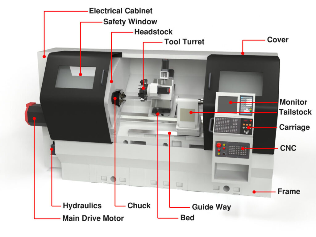
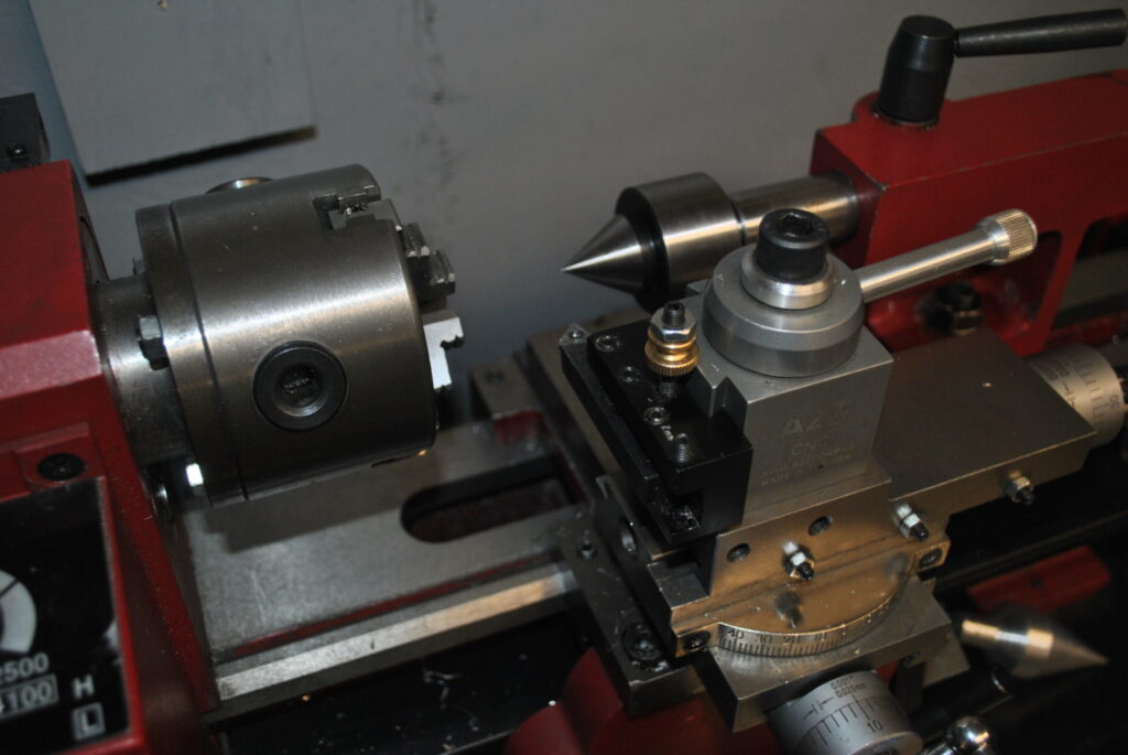
Tailstock

Most two-axis lathes come with a spindle, chuck, lathe bed, and carriage, but they might omit a tailstock as a standard feature. So, if you anticipate turning long, smaller-diameter shafts, a moveable tailstock is essential for supporting the workpiece at the end opposite the chuck and headstock. Without the tailstock’s support, you’ll likely get chatter marks or taper, making the shaft unusable. It also allows you to drill and ream holes in the center of your part.

Heavy-duty cast-iron bed and base

A heavy lathe machine enables deeper cuts, greater rigidity, and less vibration. For the longevity of the machine tool and the highest precision, always choose a lathe with a heavy-duty cast iron base rather than one made of welded steel.

Removable ways

Some lathes allow you to remove a portion of the ways below the chuck, creating a “gap.” This gap enables you to turn larger diameters since it increases the clearance for a larger swing diameter. It’s a feature you should consider.

Large diameter bore hole through the machine

When the workpiece must extend through the back of the chuck, the spindle through-hole diameter determines the maximum part diameter. Some lathes are designed with “big-bore” options, which is a feature you might need if you work on long shafts with larger diameters.

Steady rest

A steady rest is a ring with several adjustable jaws fastened to the lathe’s ways to support the workpiece. Typically the frame of the steady rest is split, with the top half of the ring being hinged, and it closes around the shaft, providing stability.

Lathe Manufacturers to Consider

Typically, this list could be divided into manual and CNC lathes, but let’s start by mentioning a reputable machine tool offering both types in one machine:

  • CNC Masters: The 1440 CNC Lathe can revert to manual control quickly and efficiently, eliminating the need to write a CNC program for short runs. Their affordable machines are built in the USA.
  • Hardinge: Founded in Chicago in the 1890s, Hardinge is an American machine tool manufacturing company with a long history of quality. Headquartered in Pennsylvania, it has a presence in 65 countries.
  • Okuma: Okuma is a Japanese machine tools brand that has been in business for over 120 years and has built a solid reputation. They have become well-known in North America, with many distributors throughout the states.
  • Haas: Haas is another American machine tool builder with a reputation for quality and affordability.
  • Mazak: The Mazak company was founded in 1919 and has become a global organization manufacturing quality lathe machines.

How much do CNC lathes cost?

As mentioned earlier, a 13 x 35.25 CNC lathe from CNC Masters with all the bells and whistles you’ll need to get started is priced at $10,695. Small CNC mini-lathes are $2,000 to $9,000, while most two-axis models range from $15,000 to $50,000. Large production lathes can go as high as $300,000 or more.

Lathe Machine Buying Tips

We’ve discussed what a lathe is and some of the technical parts. Here are the eight tips to consider before you make your next purchase:

  1. Optimal Size Selection: For precision work, choose a lathe size that’s perfect for your workpieces. This includes considering the ‘swing’ for the maximum workpiece radius, and ‘bed size’ for the distance between headstock and tailstock. A benchtop lathe might be ideal for smaller, detailed projects.
  2. Power and Space Requirements: Make sure your workspace can handle the lathe’s dimensions and weight. Also, ensure your electrical setup can support a lathe with variable speed or other power-intensive features.
  3. Matching Machine Capabilities: Align the lathe’s capabilities, such as variable speed and spindle bore, with your project requirements. This includes accommodating the maximum length and diameter of your workpieces.
  4. Understanding Lathe Varieties: Differentiate between lathe types like engine and turret lathes. Select the type that fits your material needs, whether a metalworking lathe woodworking lathe, or sanding lathe, considering features like spindle bore for enhanced versatility. You could even look for a combo lathe, a type of machine with a mill and drill press built into one machine.
  5. Choosing the Right Spindle: Opt between belt-driven or direct-drive spindles. Direct-drive offers rapid variable speed changes, whereas belt-driven models are known for their robust power and precision.
  6. Performance Specifications: Evaluate the lathe’s spindle speed, horsepower, and torque. Ensure these parameters meet the demands of your specific workpiece sizes and materials.
  7. Tooling Preparation: Prepare for additional purchases such as jaw chucks, faceplates, and a variety of turning tools for different machining tasks.

Buy a CNC Lathe That Gives You the Most Value for the Price

CNC machines are expensive but incredibly powerful machine tools that add speed and versatility to any machine shop or home workshop. CNC Masters offers two CNC lathes that meet all the speed lathe and precision lathe criteria. These CNC lathes are built in the USA and come with excellent customer support.

CNC Masters 1440 CNC Lathe

1440 CNC Lathe Machine
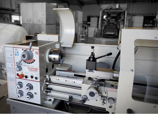
CNC capabilities transform complex manual turning applications into an easy-to-program language to run a complicated part accurately on production runs. The 1440 lathe machine features:

  • Versatile machine that instantly converts from CNC lathe to traditional engine lathe mode
  • 40″ Distance between centers with a 14″ swing over the lathe bed
  • Full 2-axis coordinated motion control on bipolar motors – true interpolation
  • Home Reference sensors on the X & Z Axis
  • 2 HP main spindle motor
  • Digital readout display of the X & Z counters in English or metric
  • CNC Masters custom software is included

About Peter Jacobs

Peter Jacobs is the Senior Director of Marketing at CNC Masters, a leading supplier of CNC mills, milling machines, and CNC lathes. He is actively involved in manufacturing processes and regularly contributes his insights for various blogs in CNC machining, 3D printing, rapid tooling, injection molding, metal casting, and manufacturing in general. You can connect with him on his LinkedIn.

Have Questions? Need a Quote?

Looking for more information about our CNC machines and services? Contact us today.

Contact

Slide 1

29. Create a Peck Drilling Program in Circular or Rectangular Patterns
Using the Circular or Rectangular Drilling Wizards, you can program the machine to drill an un-limited series of holes along the X and Y planes. Program it to drill straight through to your total depth, use a high-speed pecking cycle, or deep hole pecking cycle. You can program the cut-in depth and return point for a controlled peck drill application to maximize chip clearance.

Slide 1

20. Change up to 30 tools with compensation, and store your tool offsets for other programs
The MX supports…

Slide 1

21. Use the optional ATC rack up to 8 tools for milling, drilling, and rigid tapping applications
The CNC Masters Automatic Tool Changer Rack and Tools (US Patent 9,827,640B2) can be added to any CNC Masters Milling Machine built with the rigid tapping encoder option. The tutorial will guide you through the set-up procedure using the ATC tools.

Slide 1

22. Use the optional Rigid Tapping Wizard without the need for tapping head attachments
When you order your CNC Masters machine, have it built with the optional rigid tapping encoder. You can take any drill cycle program and replace the top line with a tapping code created by the wizard to tap your series of holes up to 1/2” in diameter.

Slide 1

23. Use the optional Digital Probe to scan the profile and/or pockets of your fun/hobby type designs to write your tool path program and machine out a duplicate of your original design To “surface” scan an object, you can program the probe along the X or Y plane. The stylus will travel over the part starting on the left side front corner of the object and work its way to the end of the part on the right side. Depending on how the stylus moves, it will record linear and interpolated movements along the X, Y, and Z planes directly on the MX Editor.
To “pocket” scan an object containing a closed pocket such as circles or squares, the scan will start from the top front, work its way inside of the pocket, and scan the entire perimeter of the pocket.
Under the Setup of the MX software you will find the Probe Tab which will allow you to calibrate and program your probe. Your “Probe Step”, “Feed”, and “Data Filter” can also be changed on the fly while the probe is in the middle of scanning your object.

Slide 1

24. Use work offsets G54-G59 for nesting applications
The work offsets offer you a way to program up to six different machining locations. It’s like having multiple 0.0 locations for different parts. This is very useful especially when using sub-routines/nesting applications.

Slide 1

25. Create a Rectangular Pocket / Slot with our selection of Wizards to help you build a tool path program
The Cycle Wizards for the mill or lathe makes it easy to create a simple tool path without needing to use a CAD and CAM software.
On this Wizard, the Rectangular Pocket / Slots, can be used to form a deep rectangular pocket into your material or machine a slot duplicating as many passes needed to its total depth.

Slide 1

26. Create a Circular Pocket Wizard
Input the total diameter, the step down, and total depth and the code will be generated.

Slide 1

27. Do Thread Milling using a single point cutter Wizard

Slide 1

28. Cut a gear out using the Cut Gear Wizard with the optional Fourth Axis

Slide 1

19. Disable the axis motors to manually hand crank each axis into place
Easily de-energize the axis motors by clicking [Disable Motors] to crank each axis by hand, and then press [Reset Control] to re-energize the axis motors.

Slide 1

30. The MX interface can easily be interchanged from Mill Mode to Lathe Mode
Use this interface for your CNC Masters Lathe. It contains all the same user-friendly features and functions that comes in Mill Mode. Simply go to the Setup page and change the interface.

Slide 1

31. Use Tool Change Compensation or the optional Auto Tool Changer Turret if your application requires more than one tool in a single program
You can offset the length and angle of each tool and record it under Tools in your Setup. The program will automatically pause the lathe’s movement and spindle allowing you to change out your tool, or allowing the optional ATC Turret to quickly turn to its next tool and continue machining.
On the MX interface, you also have four Tool Position buttons. Select your desired T position, and the auto tool post will quickly turn and lock itself to that position.

Slide 1

32. Use the Lathe Wizard Threading Cycle to help you program your lathe’s internal or external threads in inches or metric

Slide 1

33. Use the Lathe Wizard Turning / Boring Cycle to help you program simple turning and boring cycles without having to go through a CAM or writing a long program with multiple passes

Slide 1

34. Use the Lathe Wizard Peck Drilling Cycle to help you program your drill applications or for face grooving

Slide 1

35. Facing / Grooving / Part Off Cycle Wizards – with Constant Surface Speed
These cycles can be used with Constant Surface Speed allowing the spindle speed to increase automatically as the diameter of the part decreases giving your application a consistent workpiece finish. With CSS built into the wizard, there is no need to break down the cycle into multiple paths and multiple spindle speed changes.

Slide 1

36. This is our list of supported G and M codes which can be found under Tools > G Code/ M Code List in the MX
If you plan to use a third-party CAM software to generate your tool path program, use a generic FANUC post processor and edit it to match our list of codes. As an option, we also sell Visual mill/turn CAM software which comes with a guaranteed post processor for our machines to easily generate your tool path programs based on your CAD drawings.

Slide 1

37. Our pledge to you…

Slide 1

10. Run each tool path independently to study its movement
1. Run the machine on Trace mode. You can run each tool path independently, one line at a time to study the tool path movement on the machine to verify the position of the application and if any fixture/vise is in the way of the cutter’s path.

2. You can also verify your program by clicking on the Trace and Draw buttons together. This will allow you to view each tool path independently one line at a time in the Draw Window.

Slide 1

2. Clutter Free Interface
The MX is engineered for the CNC MASTERS machine so you do not have to fiddle with a detailed complicated configuration that can be overwhelming. Just load in the MX and start machining!2. Clutter Free Interface
The MX is engineered for the CNC MASTERS machine so you do not have to fiddle with a detailed complicated configuration that can be overwhelming. Just load in the MX and start machining!

Slide 1

3. Features Tour and Tutorials Included
The Features Tour will give you a quick run-down on all the features the MX can do for you. The Tutorials are easy to follow even for the first time CNC machinist.
Feel free to download the MX on any of your computers. We recommend downloading the MX along with your CAD and CAM software there at the comfort of your office computer to generate your tool path programs. You don’t need to be hooked up to the machine either to test your program in simulation mode.

Slide 1

4. Navigate and Edit Your Program through the MX interface with Ease
With a few clicks of the mouse or using touch screen technology, you can easily navigate through the MX interface importing saved programs into the Editor from the File drop down menu. Using standard windows features to edit your program you can then lock the Editor Screen to avoid accidental editing, and if you need to insert a line in the middle of a program, just click on [ReNum] to re-number your tool path list.
You can create a program or import CAM generated G-code tool paths into the Editor
The X Y and Z W arrow jog buttons are displayed from the point of view of the cutter to avoid confusion when the table and saddle are moving. You can also adjust your spindle speed and coolant control while jogging each axis.

Slide 1

5. Feed Hold – Pause in the Middle of your Program
Feed Hold lets you pause in the middle of a program. From there you can step through your program one line at time while opting to shut the spindle off and then resume your program.
You can also write PAUSE in the middle of your program and jog each axis independently while your program is in pause mode.

Slide 1

6. Hot Keys
Hot Keys is an alternative method to easily control your machine using your hard or touch screen keyboard. One can press P to pause a program, press S to turn Spindle On, G to run a program, Space Bar to Stop, J to record your individual movements one line at a time to create a program in teach mode.

Slide 1

7. Pick Menu – for conversational mode programming
Write FANUC style G-codes directly into the Editor or select commands off the [Pick] menu and write your tool path program in conversational mode such as what is written in the Editor box. You can even mix between conversation commands and G-codes in the same program.

Slide 1

8. Pick Menu List of Options
Use commands such as MOVE, SPINDLE ON/OFF, COOLANT ON/OFF, PAUSE, DELAY, GO HOME…. to write your tool path programs in conversational mode.

Slide 1

9. Draw the Tool Path to verify it before pressing Go
Hit Draw to view your tool path program drawing, check out its run time, or even simulate the tool path in 3D mode. This can be helpful to quickly verify your program before running it. You can also slow down or speed up the drawing or simulation process.
You can also hit Go within the Draw Window itself to verify the cutter’s position on the machine. The current tool path will be highlighted and simultaneously draw out the next path so you can verify what the cutter will be doing next on the program.

Slide 1

MX Software – Easy to Use, Easy to Learn – Included with your machine purchase
The MX software is designed to work seamlessly with your CNC Masters machine. It is made to work with Windows PC – desktop, laptop, or an all in one – on standard USB. Use it on Windows 8 or 10 64-bit operating systems.
No internal conversion printer/serial port to USB software or additional conversion hardware is used with the MX.

Slide 1

11. Counters display in Inches or Millimeters – Continuous Feed
1. When running a program, the counters will display a “real-time” readout while the machine is in CNC operation without counting ahead of the movement.
2. The current tool path is highlighted while the machine is in operation without causing slight interruptions/pauses as the software feeds the tool path to the machine. The MX internally interprets a program ten lines ahead to allow for “continuous machining” avoiding slight interruptions as the machine waits for its next tool path command.
3. “Run Time” tells you how long it takes to run your tool path program.

Slide 1

12. Use the “Go From Line” command to start in the middle of your program
If you ever need to begin your program from somewhere in the middle of it, use [Go From Line] which you can find under Tools. The Help guide will walk you through how to position the cutter without losing its position on the machine.

Slide 1

13. Exact Motion Distance without over-stepping on an axis while jogging
Use “Relative ON” to enter a specific coordinate to jog any of your axes to an exact location without having to write a program. It’s like using “power feed” but easier. You can jog an exact distance on any of the axes without needing to keep the key pressed down and mistakenly over-step the movement releasing your finger too slowly off the jog button.
Let’s say you need to drill a hole exactly 0.525” using the Z. So you enter 0.525 in the Z box. Next, adjust the JOG FEED RATE slider for the desired feed rate. Then “click once” on the +Z or -Z button to activate the travel. In this case you click once the -Z button first to drill the hole exactly 0.525”. Then click once on the +Z button to drive the axis back up 0.525”.

Slide 1

14. Teach Mode – Jog Input
You can create a tool path program by storing each point-to-point movement by simply jogging an axis one at a time. Click on either of the Jog Input buttons to store each movement on the Editor Screen. You can then add Spindle ON, feed commands, and press GO to run the new program as needed. This is a great feature to help you learn to create a program by the movements you make on the machine without necessarily writing out an entire program first.

Slide 1

15. Override on the fly to adjust the Jog Feed to Rapid or the Spindle Speed during the middle of a program
1. Jog Feed and Rapid with Override: You can adjust feeds using the slider from slow minimum 0.1″ per minute to a rapid of 100″ per minute of travel. You can even micro-step your jog as low as 0.01”/min. The [-][+] buttons allow you to fine tune feeds in 5% increments while the program is in motion.
2. Spindle Speed with Override: You can adjust speeds using the slider from a slow minimum RPM to the max RPM according to the machine setup. The [-][+] buttons allow you to fine tune feeds in 5% increments while the program is in motion.

Slide 1

16. Adjust Counters using Pre-Set if you cannot begin the program from 0.00
In a situation where you cannot begin your cutter at it’s 0.00 location, you can “Pre-Set” directly into the counters by typing in your beginning coordinate. You can press Go from here to run your program. You can also “zero all” or “zero” your counters independently. With one click of the [Return to 0.0] button, all axes will travel back to its respective 0.0 on the machine.

Slide 1

17. Set and Save your 0.00 position for future runs
Set and save your 0.00 position on the machine. These coordinates will be recorded as the first line of the program in the Editor Screen. Should you desire to return to this program at a later date, you only have to click on the Set Zero Return button. This will command the machine to automatically jog each axis to its saved “set” 0.00 position according to the recorded coordinates at the first line of the program.

Slide 1

18. Create a “Home” position to clear your application and run multiple times
Let’s say you need to machine one application times 100 pieces. This usually requires a jig to retain that physical 0.00 position. But in this case, you want the program to end with a clearance of the axes to easily switch out the next piece of stock and start again. With Save Home, you have the ability to save this offset (home) position while still retaining your Set Zero position where the machine will mill your part out. Pressing [Save Home] will record this new position under the Set Zero line in your program.
Pressing [Go Home] will jog your axes back to your “saved home” position where you originally pressed the Save Home command. You can also input GO_HOME from the Pick Menu as its own tool path in your program. At the completion of your program the axes will end at your Home position. Replace your part, then press [Return to 0.0] button to allow the axes to return to its zero position, and press Go to start your next run.

previous arrow
next arrow