CALL US TODAY

CALL US TODAY

A Beginner’s Guide to Tight Tolerance Machining

In precision engineering, tight-tolerance machining is a cornerstone for manufacturing processes where accuracy is not just a requirement but the lifeblood of functionality and quality control. This technique ensures components fit together flawlessly, performing at peak levels for aerospace, medical devices, and automotive applications where the line between success and failure can be as fine as a human hair.

In this article, we will examine what tight-tolerance machining entails, why it’s essential, and how to achieve it with all machine tools and in every machine shop.

What Does Tight Tolerance Mean?

Tight tolerance machining is a manufacturing process in which precision parts are produced with precise measurements. In this context, ‘tolerance’ refers to the allowable limit of variation in a physical dimension, and ‘tight’ tolerance means that this variation is minimal, often down to a thousandth of an inch or less. This extreme precision is critical in industries where even the smallest deviation from product design specifications can significantly affect the product’s performance, safety, or functionality. Aerospace, medical, automotive, and military sectors often require tight-tolerance parts because they are integral to the safety and functionality of their products. Achieving such precision requires advanced machinery, skilled operators, and meticulous quality control. Failure to adhere to these rigorous standards can compromise the integrity of the final product, highlighting the importance of tight tolerance machining in high-stakes applications.

Why Are Tighter Tolerances Necessary?

Precision machining of components ensures they accurately reflect the intended design specifications. When tolerances are stringent, the performance and reliability of these parts are significantly improved.

Consider the aerospace and automotive sectors, where high-precision parts require very tight tolerances. They guarantee that components fit together perfectly and operate according to their part design.

In contrast, if tolerances are too generous, there is a risk of improper fitting which could severely affect performance and pose safety hazards.

Manufacturers can achieve repeatability in dimensions, shapes, and other critical factors by utilizing tight-tolerance CNC machining techniques. This precision is especially vital in the medical device industry where part accuracy is synonymous with patient safety and product effectiveness.

Beyond enhancing product integrity, a strict tolerance CNC machining process brings efficiency gains to the manufacturing workflow. High-precision CNC machines can produce parts faster while reducing material wastage, saving time, and cutting costs which directly benefits the client with speedier lead times and lower prices.

How Can Machinists Achieve Even the Tightest Tolerances?

Machinists must adopt a meticulous and systematic approach to achieve the tightest tolerances. Precision machined parts result from several factors, including the machinery’s quality, the machinist’s skill level, the material used, and the techniques applied.

Machinery Quality

CNC machines offer advanced capabilities suitable for complex parts, but many machine shops still rely on conventional manual machines. These machines must be well maintained and equipped with devices, such as digital readouts (DRO), for milling and drilling accurately on milling machines and lathes.

Tool Calibration

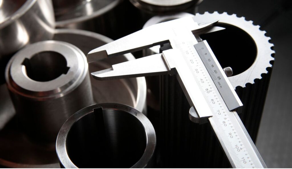
Regular tool calibration ensures optimal performance. Precise measuring instruments such as micrometers, gauges, and calipers can detect even the slightest deviations from the desired measurements specified during the design stage.

Material Selection

Understanding the properties of different materials is crucial, as they can expand or contract with temperature changes. Selecting the suitable material during the design phase can mitigate issues with tolerances on the workpiece.

Technique Refinement

Machinists should employ consistent workholding techniques to ensure stability during machining. Advanced techniques like ‘peck drilling’ or ‘climb milling’ can also produce more accurate results.

Environmental Control

Temperature fluctuations can affect both the material and machinery. Controlling the temperature and humidity is essential for minimizing thermal expansion and achieving high-quality machined parts.

Finally, continuous training and experience are invaluable. Machinists must stay informed about the latest cutting tools, techniques, and materials. By combining state-of-the-art equipment with honed skills and attention to detail, achieving tight tolerances is well within reach.

Is There a Downside to Maintaining Tight Tolerances?

While striving for tight tolerances in manufacturing ensures high levels of precision, it also introduces several challenges. The process typically demands sophisticated CNC machining services and highly skilled labor, which can significantly increase production costs. Close tolerances leave little room for error, resulting in a higher scrap rate or the need for costly rework when products deviate from the stringent standards. Additionally, the time-intensive nature of producing parts with tight tolerances can slow down the production process, potentially disrupting supply chains and market responsiveness.

Additionally, maintaining tight tolerances can limit the choice of materials since not all materials can withstand the processing required for high-precision manufacturing. In some scenarios, such intense focus on precision might be over-engineered during the design process for the product’s intended use, thus unnecessarily inflating expenses without providing proportional value to the end-user. This overemphasis on accuracy can create an imbalance, sacrificing cost-effectiveness and flexibility for marginal gains in product performance.

CNC Machining is Essential for Tight Tolerances

Tight tolerance machining benefits industries that require high levels of accuracy and consistency. Although it presents challenges such as higher costs, longer production times, and the need for advanced equipment and skilled operators, its advantages to complex and high-specification projects typically outweigh these drawbacks. It empowers manufacturers to produce parts with exceptional reliability and performance, which is indispensable in critical applications like aerospace, medical devices, and automotive manufacturing. Therefore, when precision is paramount, tight tolerance machining is beneficial and often essential.

CNC machining is appreciated for its versatility and application in both large-scale and small-scale manufacturing. Learn more in our Guide to CNC Machines or contact our team with any questions you have.

About Peter Jacobs

Peter Jacobs is the Senior Director of Marketing at CNC Masters, a leading supplier of CNC mills, milling machines, and CNC lathes. He is actively involved in manufacturing processes and regularly contributes his insights for various blogs in CNC machining, 3D printing, rapid tooling, injection molding, metal casting, and manufacturing in general. You can connect with him on his LinkedIn.

Have Questions? Need a Quote?

Looking for more information about our CNC machines and services? Contact us today.

Contact

Slide 1

29. Create a Peck Drilling Program in Circular or Rectangular Patterns
Using the Circular or Rectangular Drilling Wizards, you can program the machine to drill an un-limited series of holes along the X and Y planes. Program it to drill straight through to your total depth, use a high-speed pecking cycle, or deep hole pecking cycle. You can program the cut-in depth and return point for a controlled peck drill application to maximize chip clearance.

Slide 1

20. Change up to 30 tools with compensation, and store your tool offsets for other programs
The MX supports…

Slide 1

21. Use the optional ATC rack up to 8 tools for milling, drilling, and rigid tapping applications
The CNC Masters Automatic Tool Changer Rack and Tools (US Patent 9,827,640B2) can be added to any CNC Masters Milling Machine built with the rigid tapping encoder option. The tutorial will guide you through the set-up procedure using the ATC tools.

Slide 1

22. Use the optional Rigid Tapping Wizard without the need for tapping head attachments
When you order your CNC Masters machine, have it built with the optional rigid tapping encoder. You can take any drill cycle program and replace the top line with a tapping code created by the wizard to tap your series of holes up to 1/2” in diameter.

Slide 1

23. Use the optional Digital Probe to scan the profile and/or pockets of your fun/hobby type designs to write your tool path program and machine out a duplicate of your original design To “surface” scan an object, you can program the probe along the X or Y plane. The stylus will travel over the part starting on the left side front corner of the object and work its way to the end of the part on the right side. Depending on how the stylus moves, it will record linear and interpolated movements along the X, Y, and Z planes directly on the MX Editor.
To “pocket” scan an object containing a closed pocket such as circles or squares, the scan will start from the top front, work its way inside of the pocket, and scan the entire perimeter of the pocket.
Under the Setup of the MX software you will find the Probe Tab which will allow you to calibrate and program your probe. Your “Probe Step”, “Feed”, and “Data Filter” can also be changed on the fly while the probe is in the middle of scanning your object.

Slide 1

24. Use work offsets G54-G59 for nesting applications
The work offsets offer you a way to program up to six different machining locations. It’s like having multiple 0.0 locations for different parts. This is very useful especially when using sub-routines/nesting applications.

Slide 1

25. Create a Rectangular Pocket / Slot with our selection of Wizards to help you build a tool path program
The Cycle Wizards for the mill or lathe makes it easy to create a simple tool path without needing to use a CAD and CAM software.
On this Wizard, the Rectangular Pocket / Slots, can be used to form a deep rectangular pocket into your material or machine a slot duplicating as many passes needed to its total depth.

Slide 1

26. Create a Circular Pocket Wizard
Input the total diameter, the step down, and total depth and the code will be generated.

Slide 1

27. Do Thread Milling using a single point cutter Wizard

Slide 1

28. Cut a gear out using the Cut Gear Wizard with the optional Fourth Axis

Slide 1

19. Disable the axis motors to manually hand crank each axis into place
Easily de-energize the axis motors by clicking [Disable Motors] to crank each axis by hand, and then press [Reset Control] to re-energize the axis motors.

Slide 1

30. The MX interface can easily be interchanged from Mill Mode to Lathe Mode
Use this interface for your CNC Masters Lathe. It contains all the same user-friendly features and functions that comes in Mill Mode. Simply go to the Setup page and change the interface.

Slide 1

31. Use Tool Change Compensation or the optional Auto Tool Changer Turret if your application requires more than one tool in a single program
You can offset the length and angle of each tool and record it under Tools in your Setup. The program will automatically pause the lathe’s movement and spindle allowing you to change out your tool, or allowing the optional ATC Turret to quickly turn to its next tool and continue machining.
On the MX interface, you also have four Tool Position buttons. Select your desired T position, and the auto tool post will quickly turn and lock itself to that position.

Slide 1

32. Use the Lathe Wizard Threading Cycle to help you program your lathe’s internal or external threads in inches or metric

Slide 1

33. Use the Lathe Wizard Turning / Boring Cycle to help you program simple turning and boring cycles without having to go through a CAM or writing a long program with multiple passes

Slide 1

34. Use the Lathe Wizard Peck Drilling Cycle to help you program your drill applications or for face grooving

Slide 1

35. Facing / Grooving / Part Off Cycle Wizards – with Constant Surface Speed
These cycles can be used with Constant Surface Speed allowing the spindle speed to increase automatically as the diameter of the part decreases giving your application a consistent workpiece finish. With CSS built into the wizard, there is no need to break down the cycle into multiple paths and multiple spindle speed changes.

Slide 1

36. This is our list of supported G and M codes which can be found under Tools > G Code/ M Code List in the MX
If you plan to use a third-party CAM software to generate your tool path program, use a generic FANUC post processor and edit it to match our list of codes. As an option, we also sell Visual mill/turn CAM software which comes with a guaranteed post processor for our machines to easily generate your tool path programs based on your CAD drawings.

Slide 1

37. Our pledge to you…

Slide 1

10. Run each tool path independently to study its movement
1. Run the machine on Trace mode. You can run each tool path independently, one line at a time to study the tool path movement on the machine to verify the position of the application and if any fixture/vise is in the way of the cutter’s path.

2. You can also verify your program by clicking on the Trace and Draw buttons together. This will allow you to view each tool path independently one line at a time in the Draw Window.

Slide 1

2. Clutter Free Interface
The MX is engineered for the CNC MASTERS machine so you do not have to fiddle with a detailed complicated configuration that can be overwhelming. Just load in the MX and start machining!2. Clutter Free Interface
The MX is engineered for the CNC MASTERS machine so you do not have to fiddle with a detailed complicated configuration that can be overwhelming. Just load in the MX and start machining!

Slide 1

3. Features Tour and Tutorials Included
The Features Tour will give you a quick run-down on all the features the MX can do for you. The Tutorials are easy to follow even for the first time CNC machinist.
Feel free to download the MX on any of your computers. We recommend downloading the MX along with your CAD and CAM software there at the comfort of your office computer to generate your tool path programs. You don’t need to be hooked up to the machine either to test your program in simulation mode.

Slide 1

4. Navigate and Edit Your Program through the MX interface with Ease
With a few clicks of the mouse or using touch screen technology, you can easily navigate through the MX interface importing saved programs into the Editor from the File drop down menu. Using standard windows features to edit your program you can then lock the Editor Screen to avoid accidental editing, and if you need to insert a line in the middle of a program, just click on [ReNum] to re-number your tool path list.
You can create a program or import CAM generated G-code tool paths into the Editor
The X Y and Z W arrow jog buttons are displayed from the point of view of the cutter to avoid confusion when the table and saddle are moving. You can also adjust your spindle speed and coolant control while jogging each axis.

Slide 1

5. Feed Hold – Pause in the Middle of your Program
Feed Hold lets you pause in the middle of a program. From there you can step through your program one line at time while opting to shut the spindle off and then resume your program.
You can also write PAUSE in the middle of your program and jog each axis independently while your program is in pause mode.

Slide 1

6. Hot Keys
Hot Keys is an alternative method to easily control your machine using your hard or touch screen keyboard. One can press P to pause a program, press S to turn Spindle On, G to run a program, Space Bar to Stop, J to record your individual movements one line at a time to create a program in teach mode.

Slide 1

7. Pick Menu – for conversational mode programming
Write FANUC style G-codes directly into the Editor or select commands off the [Pick] menu and write your tool path program in conversational mode such as what is written in the Editor box. You can even mix between conversation commands and G-codes in the same program.

Slide 1

8. Pick Menu List of Options
Use commands such as MOVE, SPINDLE ON/OFF, COOLANT ON/OFF, PAUSE, DELAY, GO HOME…. to write your tool path programs in conversational mode.

Slide 1

9. Draw the Tool Path to verify it before pressing Go
Hit Draw to view your tool path program drawing, check out its run time, or even simulate the tool path in 3D mode. This can be helpful to quickly verify your program before running it. You can also slow down or speed up the drawing or simulation process.
You can also hit Go within the Draw Window itself to verify the cutter’s position on the machine. The current tool path will be highlighted and simultaneously draw out the next path so you can verify what the cutter will be doing next on the program.

Slide 1

MX Software – Easy to Use, Easy to Learn – Included with your machine purchase
The MX software is designed to work seamlessly with your CNC Masters machine. It is made to work with Windows PC – desktop, laptop, or an all in one – on standard USB. Use it on Windows 8 or 10 64-bit operating systems.
No internal conversion printer/serial port to USB software or additional conversion hardware is used with the MX.

Slide 1

11. Counters display in Inches or Millimeters – Continuous Feed
1. When running a program, the counters will display a “real-time” readout while the machine is in CNC operation without counting ahead of the movement.
2. The current tool path is highlighted while the machine is in operation without causing slight interruptions/pauses as the software feeds the tool path to the machine. The MX internally interprets a program ten lines ahead to allow for “continuous machining” avoiding slight interruptions as the machine waits for its next tool path command.
3. “Run Time” tells you how long it takes to run your tool path program.

Slide 1

12. Use the “Go From Line” command to start in the middle of your program
If you ever need to begin your program from somewhere in the middle of it, use [Go From Line] which you can find under Tools. The Help guide will walk you through how to position the cutter without losing its position on the machine.

Slide 1

13. Exact Motion Distance without over-stepping on an axis while jogging
Use “Relative ON” to enter a specific coordinate to jog any of your axes to an exact location without having to write a program. It’s like using “power feed” but easier. You can jog an exact distance on any of the axes without needing to keep the key pressed down and mistakenly over-step the movement releasing your finger too slowly off the jog button.
Let’s say you need to drill a hole exactly 0.525” using the Z. So you enter 0.525 in the Z box. Next, adjust the JOG FEED RATE slider for the desired feed rate. Then “click once” on the +Z or -Z button to activate the travel. In this case you click once the -Z button first to drill the hole exactly 0.525”. Then click once on the +Z button to drive the axis back up 0.525”.

Slide 1

14. Teach Mode – Jog Input
You can create a tool path program by storing each point-to-point movement by simply jogging an axis one at a time. Click on either of the Jog Input buttons to store each movement on the Editor Screen. You can then add Spindle ON, feed commands, and press GO to run the new program as needed. This is a great feature to help you learn to create a program by the movements you make on the machine without necessarily writing out an entire program first.

Slide 1

15. Override on the fly to adjust the Jog Feed to Rapid or the Spindle Speed during the middle of a program
1. Jog Feed and Rapid with Override: You can adjust feeds using the slider from slow minimum 0.1″ per minute to a rapid of 100″ per minute of travel. You can even micro-step your jog as low as 0.01”/min. The [-][+] buttons allow you to fine tune feeds in 5% increments while the program is in motion.
2. Spindle Speed with Override: You can adjust speeds using the slider from a slow minimum RPM to the max RPM according to the machine setup. The [-][+] buttons allow you to fine tune feeds in 5% increments while the program is in motion.

Slide 1

16. Adjust Counters using Pre-Set if you cannot begin the program from 0.00
In a situation where you cannot begin your cutter at it’s 0.00 location, you can “Pre-Set” directly into the counters by typing in your beginning coordinate. You can press Go from here to run your program. You can also “zero all” or “zero” your counters independently. With one click of the [Return to 0.0] button, all axes will travel back to its respective 0.0 on the machine.

Slide 1

17. Set and Save your 0.00 position for future runs
Set and save your 0.00 position on the machine. These coordinates will be recorded as the first line of the program in the Editor Screen. Should you desire to return to this program at a later date, you only have to click on the Set Zero Return button. This will command the machine to automatically jog each axis to its saved “set” 0.00 position according to the recorded coordinates at the first line of the program.

Slide 1

18. Create a “Home” position to clear your application and run multiple times
Let’s say you need to machine one application times 100 pieces. This usually requires a jig to retain that physical 0.00 position. But in this case, you want the program to end with a clearance of the axes to easily switch out the next piece of stock and start again. With Save Home, you have the ability to save this offset (home) position while still retaining your Set Zero position where the machine will mill your part out. Pressing [Save Home] will record this new position under the Set Zero line in your program.
Pressing [Go Home] will jog your axes back to your “saved home” position where you originally pressed the Save Home command. You can also input GO_HOME from the Pick Menu as its own tool path in your program. At the completion of your program the axes will end at your Home position. Replace your part, then press [Return to 0.0] button to allow the axes to return to its zero position, and press Go to start your next run.

previous arrow
next arrow