CALL US TODAY

CALL US TODAY

wire EDM machine

Wire EDM Machine Buyer’s Guide

Electrical discharge machining (EDM) is a process that applies CNC technology with electrical sparks to form simple or complex shapes. Sometimes referred to as spark machining, EDM creates profiles when current discharges and sparks occur between two electrodes—the wire and the workpiece. As the wire moves through the workpiece, it cuts the desired shape, and eventually, the material detaches it from the workpiece.

Here is what you need to know before purchasing your first or next CNC wire EDM.

How Does Electrical Discharge Machining Work?

As mentioned, electrical discharge machining begins when a spark is created between two electrodes, producing temperatures reaching 8000 to 12000 degrees Celsius and vaporizing the conductive material. These electrical current discharges are continuous, in a tiny gap between the two electrodes. This spark gap is maintained by the EDM machine’s controls, ensuring a constant distance as the discharge occurs millions of times per second.

The spark is controlled with high precision and restricted to only involve the workpiece’s surface and does not affect heat treating below the surface. The wire, workpiece, and electric spark are submerged in dielectric fluid, usually deionized water,

The conductivity of the deionized water is carefully controlled, creating an ideal environment for the EDM process. The deionized water also provides cooling during the wire-erosion process, as it is sometimes called, and it flushes away the tiny metal particles.

Electrical discharge machining is considered a non-traditional machining method, in contrast to traditional CNC machining methods such as drilling, milling, and threading. Wire EDM uses a wire as the tool electrode, and the wire is wound between two spools. As the wire moves through the metal, the spools supply fresh wire. Depending on how fast the wire is replaced, wire consumption could be one of the main expenses of the EDM process.

wire edm machine diagram
Diagram of a wire EDM machine

What are the Two Main Types of EDM Machines?

There are two primary types of EDM, wire and sinker EDM, sometimes called ram EDM. However, our focus will be on the wire EDM machine and the wire-cut EDM process. Each EDM works differently, so here is a brief look at both EDM machine tools:

Conventional EDM Machines

You will hear conventional EDM, also called ram EDM, sinker EDM, die sinking, and cavity-type EDM. Suitable for creating complex shapes, the process involves precision machining graphite electrodes with conventional machining methods, such as CNC mills and lathes. The electrode is a negative impression of the cavity and will form and burn or “sink” into the workpiece.

A lesser-known EDM, similar to the ram EDM machine, is the small-hole EDM that uses cylindrical electrodes to machine holes.

Wire EDM Machines

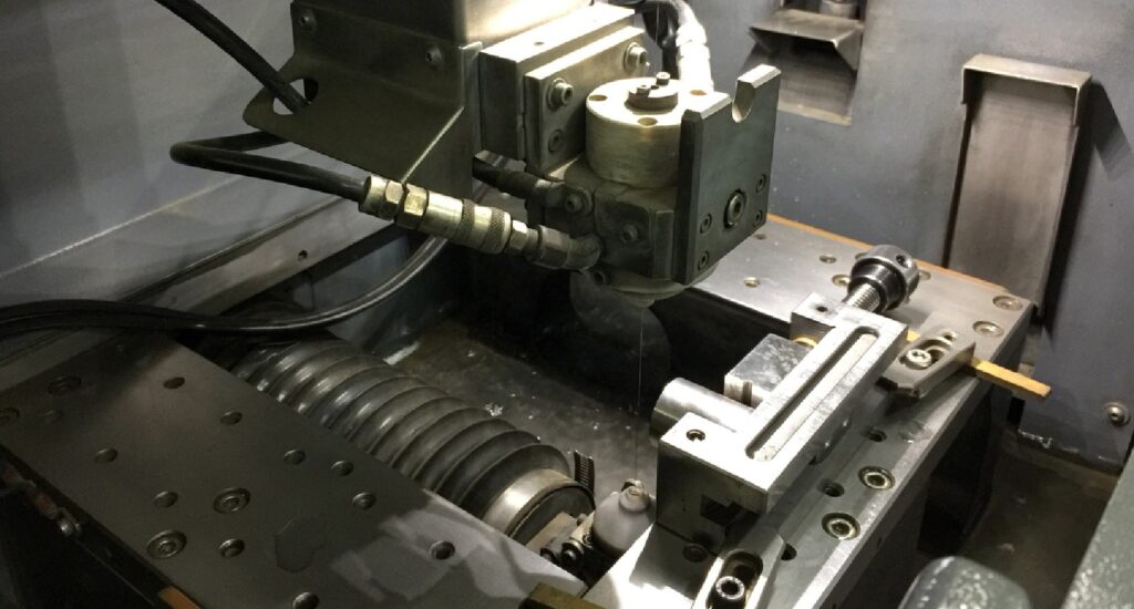
Unlike ram EDM, wire EDM, or spark-eroding EDM, employs a thin heated wire as the electrode and creates a shape through wire erosion and burning. Diamond guides hold the wire steady as it moves through the workpiece to form a specific shape without touching the metal. An automated feeder allows the wire to continuously unspool, ensuring the wire is available for a smooth and uninterrupted shape.

Occasionally, the wire EDM process requires a cut through the middle of the workpiece instead of from the outside. When that happens, the aforementioned hole-drilling EDM is used to burn a “starter hole” in the metal so the wire can be threaded through the workpiece.

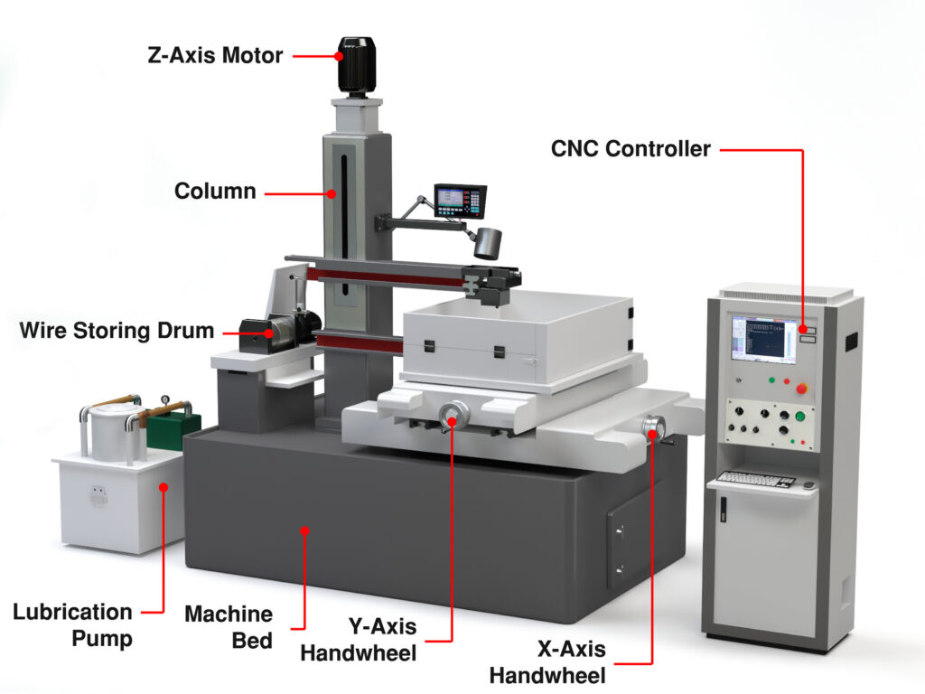
What are the Components Of A Wire EDM Machine?

The machine comprises several parts that work together to give a material the desired shape. Below are the components of the machine.

1. CNC EDM Controls

The CNC automation controls the wire EDM machining process, including the sequencing of the wire path and managing the cutting process automatically.

2. Power Supply

The power supply unit provides pulses (from 100V to 300V) to the wire electrode and the workpiece. It also controls the frequency and strength of the electrical charges passing through the wire electrode to interact with the workpiece. A quality power supply unit delivers the required charges during wire EDM machining.

3. Wire

A graphite electrode removes even hard materials with die-sinking EDM, but the wire serves as the electrode to create the electrical discharge during wire EDM. The shape and thickness of the workpiece directly influence the wire’s diameter, typically ranging from 0.05 to 0.25mm. The main types of wires include brass, zinc-coated, and diffusion-annealed wires.

4. Dielectric Medium

The wire-cut EDM process must be completed in a tank filled with dielectric fluid, preventing the workpiece particles from attaching to the wire. The medium used most often is deionized water which cools the process and gives the workpiece an excellent surface finish.

5. Electrodes

The electrodes in the machine are the wire and workpiece. The servo motor controls the wire electrode, ensuring it does not come in contact with the workpiece electrode anytime during the wire EDM cutting process.

How Do I Choose the Right Wire for My Project?

Getting the right spark erosion comes from choosing the right EDM wire for your project. Consider the following EDM wire properties:

Tensile strength

Tensile strength refers to the wire’s ability to resist stretching and breaking. High-tensile EDM wire offers the best edge straightness, making it an excellent choice for single-pass parts and in smaller diameter wires to reduce breakage. High-tensile wire works well whenever straightness, accuracy, and a fine surface finish are required.

Fracture resistance

Fracture resistance describes the wire’s resilience or toughness and its ability to resist the effects of the active environment surrounding the spark gap.

Conductivity

Conductivity measures the wire’s ability to carry an electrical current, and the higher the wire’s conductivity, the more power it can deliver to the workpiece. Because high conductivity is more efficient, cutting speeds are typically increased.

Vaporization temperature

A low vaporization temperature of the wire aids in flushing the particles from the spark gap, which is already tiny enough without having these “chips” take up room. As a result, moly and tungsten wires, with their higher vaporization temperatures, cut more slowly and flush poorly. However, they are satisfactory for roughing cuts where speed is not an issue. Even though melting produces particles, low-temp electrode alloys carry more water and contaminants away from the gap, aiding in flushing.

Hardness

Hardness is not the same as tensile strength. Instead, it refers to the wire’s ductility or ability to undergo elongation. EDM wires are either soft or hard, with the hard wire threading better than a softer wire and a soft wire taper-cutting better. A hard wire will also provide the best auto-threading reliability.

What is a Wire EDM Machine Used For?

Wire-EDM has developed into micromachining technology with precision beyond the reach of general machining. And the processing range is also relatively broad since practically any metal-conductive material can be managed without regard to the material’s hardness. Wire EDM is considered one of the most cost-effective methods for machining hard and conductive materials. Unlike conventional machining methods, wire EDM does not produce high driving force, resulting in relatively accurate and high-speed machining. This fact helps to explain why wire EDM is becoming popular with manufacturers.

Here is a list of its other advantages:

  • Wire EDM creates simple or complex shapes that would be challenging to produce with conventional machining centers and cutting tools.
  • CNC-controlled cutting works on many stainless steel alloys while maintaining a low Ra surface roughness
  • Dimensional accuracy for tight-tolerance parts
  • No contact between the wire and the workpiece, allowing for the machining of fragile sections and weak materials.
  • The process leaves few burrs
  • Custom tooling is typically not required
  • The working fluid of wire EDM is non-flammable, allowing for unmanned operation, while automatic control enhances the ease of use.
  • No high-impact cutting to create stresses that can deform the material.
  • Because wire-cut EDM efficiently processes any conductive material, it takes less time and reduces waste and cleanup time.
  • EDM is applicable for machining small parts and highly detailed parts that are too delicate for other machining methods.
  • It works for single-piece prototyping.

Are There Drawbacks to CNC EDM?

Although wire EDM offers many benefits to manufacturing companies, there are also disadvantages:

  • It is only compatible with materials that conduct electricity.
  • Composite or dielectric-coated materials are not candidates for wire EDM.
  • An oxide layer can develop on the cut surface of some materials, causing expensive additional finishing operations.
  • EDM requires a high initial investment and maintenance costs.

What are Some Applications for Wire EDM?

Although many industries use wire EDM machines for prototyping and production runs, the following three represent the industries that are most likely to use them:

Aerospace Industry

Wire EDM produces tight-tolerance parts and components, an essential requirement for aerospace part manufacturing. Along with the waterjet cutting process, EDM is the choice for creating pieces that will not withstand the high temperature and stress associated with traditional machining processes.

Aerospace industry parts, including turbine blades and landing gear components, rely on an excellent surface finish and must be highly accurate. Manufacturers have been using the wire-EDM process for many years with exceptional results.

Automotive Industry

Automotive parts often have complex shapes and are produced from hard materials. Because of this, they prefer wire EDM machines that do not rely on mechanical forces to make their parts. The wire EDM process applies to creating holes, cavities, and custom parts like bumpers, dashboards, and car doors.

Medical Industry

Wire EDM machines produce complex and accurate parts for all medical fields, including optometry and dentistry. The metals that work well with wire EDM machines are often used to make medical equipment.

Because the wire’s diameter determines the cut’s size, the wire EDM machine can add tiny features to parts like dental implants and syringe components without endangering their structural integrity.

What Materials Can Be Cut Using Wire-EDM?

You can cut any conductive material, including, but not limited to, carbon steel, stainless steel, titanium, aluminum, brass, bronze, Hastelloy, high-alloy steel, Inconel, tungsten, and more. Because of its accuracy, the EDM wire-cut method has become preferred in all industries.

Regardless of the material type, many machine parts can be produced quickly using EDM wire. However, creating parts or prototypes will depend on the workpiece’s dimensions, thickness, and length.

What are Some of the Most Reputable Wire-EDM Brands?

The following wire-EDM brands have stellar reputations, but the best wire-EDM machine for your specific operation will depend on the type of parts you intend to produce. Many claim that Makino offers the best wire EDM machines in 2023 because of their speed, accuracy, and ease of use.

Nonetheless, all the machine tool brands are on this list because they have shown superior performance over time. Here are the top five wire EDM machine manufacturers for 2023:

1. Makino

Makino is well-respected throughout the machine tool industry for their high-quality CNC machines. Their wire EDM machines are no exception with more than a dozen wire EDM models from which to choose.

2. Mitsubishi

Mitsubishi offers five separate lines of wire EDM machines, and their MX600 has the highest accuracy level and can produce the smallest possible parts of all their models.

3. FANUC

The wire EDM machines offered by FANUC are marketed under the proprietary name, ROBOCUT. FANUC has three ROBOCUT models: a small model for compact parts, a medium-sized all-around model, and a model for larger parts.

4. ONA

ONA has four series of wire EDM machines: compact, modular, hole-drilling, and custom models. Their compact options have smaller footprints but deliver high-precision cuts. Their modular wire EDM machines are known for their flexibility. ONA can supply a wire EDM machine for most applications, part sizes, and geometries.

5. Sodick

Sodick offers six different wire EDM machines, at least one of which can accommodate any size part. Each of the machines is linear-motor driven, resulting in vibration-free operation and zero backlash, enabling high-accuracy cutting and fine surface finishes. Sodick is the only company in the EDM industry to guarantee the positional accuracy of their wire EDM machines for 10 years.

How Much Does a Wire EDM Machine Cost?

A new AgieCharmilles CUT C 350 Wire EDM has a starting price of $99,000, while more popular brands will be closer to the $125,000 to $150,000 price range. For comparison, a 2020 Makino U3 Wire EDM Machine sells for $100,000, a 2000 Mitsubishi RA90 Wire Cut is $19,500, and a 2004 Makino U86 is priced at just under $50,000.

Conclusion

Wire EDM is a versatile and precise machining process that produces complex shapes and geometries. A favorite of the automotive, aerospace, and medical industries, where parts need to meet tight tolerances, wire EDM, can also be used to create prototypes or single pieces. We hope this article has given you a better understanding and appreciation of this unique and essential machine tool!

About Peter Jacobs

Peter Jacobs is the Senior Director of Marketing at CNC Masters, a leading supplier of CNC mills, milling machines, and CNC lathes. He is actively involved in manufacturing processes and regularly contributes his insights for various blogs in CNC machining, 3D printing, rapid tooling, injection molding, metal casting, and manufacturing in general. You can connect with him on his LinkedIn.

Have Questions? Need a Quote?

Looking for more information about our CNC machines and services? Contact us today.

Contact

Slide 1

29. Create a Peck Drilling Program in Circular or Rectangular Patterns
Using the Circular or Rectangular Drilling Wizards, you can program the machine to drill an un-limited series of holes along the X and Y planes. Program it to drill straight through to your total depth, use a high-speed pecking cycle, or deep hole pecking cycle. You can program the cut-in depth and return point for a controlled peck drill application to maximize chip clearance.

Slide 1

20. Change up to 30 tools with compensation, and store your tool offsets for other programs
The MX supports…

Slide 1

21. Use the optional ATC rack up to 8 tools for milling, drilling, and rigid tapping applications
The CNC Masters Automatic Tool Changer Rack and Tools (US Patent 9,827,640B2) can be added to any CNC Masters Milling Machine built with the rigid tapping encoder option. The tutorial will guide you through the set-up procedure using the ATC tools.

Slide 1

22. Use the optional Rigid Tapping Wizard without the need for tapping head attachments
When you order your CNC Masters machine, have it built with the optional rigid tapping encoder. You can take any drill cycle program and replace the top line with a tapping code created by the wizard to tap your series of holes up to 1/2” in diameter.

Slide 1

23. Use the optional Digital Probe to scan the profile and/or pockets of your fun/hobby type designs to write your tool path program and machine out a duplicate of your original design To “surface” scan an object, you can program the probe along the X or Y plane. The stylus will travel over the part starting on the left side front corner of the object and work its way to the end of the part on the right side. Depending on how the stylus moves, it will record linear and interpolated movements along the X, Y, and Z planes directly on the MX Editor.
To “pocket” scan an object containing a closed pocket such as circles or squares, the scan will start from the top front, work its way inside of the pocket, and scan the entire perimeter of the pocket.
Under the Setup of the MX software you will find the Probe Tab which will allow you to calibrate and program your probe. Your “Probe Step”, “Feed”, and “Data Filter” can also be changed on the fly while the probe is in the middle of scanning your object.

Slide 1

24. Use work offsets G54-G59 for nesting applications
The work offsets offer you a way to program up to six different machining locations. It’s like having multiple 0.0 locations for different parts. This is very useful especially when using sub-routines/nesting applications.

Slide 1

25. Create a Rectangular Pocket / Slot with our selection of Wizards to help you build a tool path program
The Cycle Wizards for the mill or lathe makes it easy to create a simple tool path without needing to use a CAD and CAM software.
On this Wizard, the Rectangular Pocket / Slots, can be used to form a deep rectangular pocket into your material or machine a slot duplicating as many passes needed to its total depth.

Slide 1

26. Create a Circular Pocket Wizard
Input the total diameter, the step down, and total depth and the code will be generated.

Slide 1

27. Do Thread Milling using a single point cutter Wizard

Slide 1

28. Cut a gear out using the Cut Gear Wizard with the optional Fourth Axis

Slide 1

19. Disable the axis motors to manually hand crank each axis into place
Easily de-energize the axis motors by clicking [Disable Motors] to crank each axis by hand, and then press [Reset Control] to re-energize the axis motors.

Slide 1

30. The MX interface can easily be interchanged from Mill Mode to Lathe Mode
Use this interface for your CNC Masters Lathe. It contains all the same user-friendly features and functions that comes in Mill Mode. Simply go to the Setup page and change the interface.

Slide 1

31. Use Tool Change Compensation or the optional Auto Tool Changer Turret if your application requires more than one tool in a single program
You can offset the length and angle of each tool and record it under Tools in your Setup. The program will automatically pause the lathe’s movement and spindle allowing you to change out your tool, or allowing the optional ATC Turret to quickly turn to its next tool and continue machining.
On the MX interface, you also have four Tool Position buttons. Select your desired T position, and the auto tool post will quickly turn and lock itself to that position.

Slide 1

32. Use the Lathe Wizard Threading Cycle to help you program your lathe’s internal or external threads in inches or metric

Slide 1

33. Use the Lathe Wizard Turning / Boring Cycle to help you program simple turning and boring cycles without having to go through a CAM or writing a long program with multiple passes

Slide 1

34. Use the Lathe Wizard Peck Drilling Cycle to help you program your drill applications or for face grooving

Slide 1

35. Facing / Grooving / Part Off Cycle Wizards – with Constant Surface Speed
These cycles can be used with Constant Surface Speed allowing the spindle speed to increase automatically as the diameter of the part decreases giving your application a consistent workpiece finish. With CSS built into the wizard, there is no need to break down the cycle into multiple paths and multiple spindle speed changes.

Slide 1

36. This is our list of supported G and M codes which can be found under Tools > G Code/ M Code List in the MX
If you plan to use a third-party CAM software to generate your tool path program, use a generic FANUC post processor and edit it to match our list of codes. As an option, we also sell Visual mill/turn CAM software which comes with a guaranteed post processor for our machines to easily generate your tool path programs based on your CAD drawings.

Slide 1

37. Our pledge to you…

Slide 1

10. Run each tool path independently to study its movement
1. Run the machine on Trace mode. You can run each tool path independently, one line at a time to study the tool path movement on the machine to verify the position of the application and if any fixture/vise is in the way of the cutter’s path.

2. You can also verify your program by clicking on the Trace and Draw buttons together. This will allow you to view each tool path independently one line at a time in the Draw Window.

Slide 1

2. Clutter Free Interface
The MX is engineered for the CNC MASTERS machine so you do not have to fiddle with a detailed complicated configuration that can be overwhelming. Just load in the MX and start machining!2. Clutter Free Interface
The MX is engineered for the CNC MASTERS machine so you do not have to fiddle with a detailed complicated configuration that can be overwhelming. Just load in the MX and start machining!

Slide 1

3. Features Tour and Tutorials Included
The Features Tour will give you a quick run-down on all the features the MX can do for you. The Tutorials are easy to follow even for the first time CNC machinist.
Feel free to download the MX on any of your computers. We recommend downloading the MX along with your CAD and CAM software there at the comfort of your office computer to generate your tool path programs. You don’t need to be hooked up to the machine either to test your program in simulation mode.

Slide 1

4. Navigate and Edit Your Program through the MX interface with Ease
With a few clicks of the mouse or using touch screen technology, you can easily navigate through the MX interface importing saved programs into the Editor from the File drop down menu. Using standard windows features to edit your program you can then lock the Editor Screen to avoid accidental editing, and if you need to insert a line in the middle of a program, just click on [ReNum] to re-number your tool path list.
You can create a program or import CAM generated G-code tool paths into the Editor
The X Y and Z W arrow jog buttons are displayed from the point of view of the cutter to avoid confusion when the table and saddle are moving. You can also adjust your spindle speed and coolant control while jogging each axis.

Slide 1

5. Feed Hold – Pause in the Middle of your Program
Feed Hold lets you pause in the middle of a program. From there you can step through your program one line at time while opting to shut the spindle off and then resume your program.
You can also write PAUSE in the middle of your program and jog each axis independently while your program is in pause mode.

Slide 1

6. Hot Keys
Hot Keys is an alternative method to easily control your machine using your hard or touch screen keyboard. One can press P to pause a program, press S to turn Spindle On, G to run a program, Space Bar to Stop, J to record your individual movements one line at a time to create a program in teach mode.

Slide 1

7. Pick Menu – for conversational mode programming
Write FANUC style G-codes directly into the Editor or select commands off the [Pick] menu and write your tool path program in conversational mode such as what is written in the Editor box. You can even mix between conversation commands and G-codes in the same program.

Slide 1

8. Pick Menu List of Options
Use commands such as MOVE, SPINDLE ON/OFF, COOLANT ON/OFF, PAUSE, DELAY, GO HOME…. to write your tool path programs in conversational mode.

Slide 1

9. Draw the Tool Path to verify it before pressing Go
Hit Draw to view your tool path program drawing, check out its run time, or even simulate the tool path in 3D mode. This can be helpful to quickly verify your program before running it. You can also slow down or speed up the drawing or simulation process.
You can also hit Go within the Draw Window itself to verify the cutter’s position on the machine. The current tool path will be highlighted and simultaneously draw out the next path so you can verify what the cutter will be doing next on the program.

Slide 1

MX Software – Easy to Use, Easy to Learn – Included with your machine purchase
The MX software is designed to work seamlessly with your CNC Masters machine. It is made to work with Windows PC – desktop, laptop, or an all in one – on standard USB. Use it on Windows 8 or 10 64-bit operating systems.
No internal conversion printer/serial port to USB software or additional conversion hardware is used with the MX.

Slide 1

11. Counters display in Inches or Millimeters – Continuous Feed
1. When running a program, the counters will display a “real-time” readout while the machine is in CNC operation without counting ahead of the movement.
2. The current tool path is highlighted while the machine is in operation without causing slight interruptions/pauses as the software feeds the tool path to the machine. The MX internally interprets a program ten lines ahead to allow for “continuous machining” avoiding slight interruptions as the machine waits for its next tool path command.
3. “Run Time” tells you how long it takes to run your tool path program.

Slide 1

12. Use the “Go From Line” command to start in the middle of your program
If you ever need to begin your program from somewhere in the middle of it, use [Go From Line] which you can find under Tools. The Help guide will walk you through how to position the cutter without losing its position on the machine.

Slide 1

13. Exact Motion Distance without over-stepping on an axis while jogging
Use “Relative ON” to enter a specific coordinate to jog any of your axes to an exact location without having to write a program. It’s like using “power feed” but easier. You can jog an exact distance on any of the axes without needing to keep the key pressed down and mistakenly over-step the movement releasing your finger too slowly off the jog button.
Let’s say you need to drill a hole exactly 0.525” using the Z. So you enter 0.525 in the Z box. Next, adjust the JOG FEED RATE slider for the desired feed rate. Then “click once” on the +Z or -Z button to activate the travel. In this case you click once the -Z button first to drill the hole exactly 0.525”. Then click once on the +Z button to drive the axis back up 0.525”.

Slide 1

14. Teach Mode – Jog Input
You can create a tool path program by storing each point-to-point movement by simply jogging an axis one at a time. Click on either of the Jog Input buttons to store each movement on the Editor Screen. You can then add Spindle ON, feed commands, and press GO to run the new program as needed. This is a great feature to help you learn to create a program by the movements you make on the machine without necessarily writing out an entire program first.

Slide 1

15. Override on the fly to adjust the Jog Feed to Rapid or the Spindle Speed during the middle of a program
1. Jog Feed and Rapid with Override: You can adjust feeds using the slider from slow minimum 0.1″ per minute to a rapid of 100″ per minute of travel. You can even micro-step your jog as low as 0.01”/min. The [-][+] buttons allow you to fine tune feeds in 5% increments while the program is in motion.
2. Spindle Speed with Override: You can adjust speeds using the slider from a slow minimum RPM to the max RPM according to the machine setup. The [-][+] buttons allow you to fine tune feeds in 5% increments while the program is in motion.

Slide 1

16. Adjust Counters using Pre-Set if you cannot begin the program from 0.00
In a situation where you cannot begin your cutter at it’s 0.00 location, you can “Pre-Set” directly into the counters by typing in your beginning coordinate. You can press Go from here to run your program. You can also “zero all” or “zero” your counters independently. With one click of the [Return to 0.0] button, all axes will travel back to its respective 0.0 on the machine.

Slide 1

17. Set and Save your 0.00 position for future runs
Set and save your 0.00 position on the machine. These coordinates will be recorded as the first line of the program in the Editor Screen. Should you desire to return to this program at a later date, you only have to click on the Set Zero Return button. This will command the machine to automatically jog each axis to its saved “set” 0.00 position according to the recorded coordinates at the first line of the program.

Slide 1

18. Create a “Home” position to clear your application and run multiple times
Let’s say you need to machine one application times 100 pieces. This usually requires a jig to retain that physical 0.00 position. But in this case, you want the program to end with a clearance of the axes to easily switch out the next piece of stock and start again. With Save Home, you have the ability to save this offset (home) position while still retaining your Set Zero position where the machine will mill your part out. Pressing [Save Home] will record this new position under the Set Zero line in your program.
Pressing [Go Home] will jog your axes back to your “saved home” position where you originally pressed the Save Home command. You can also input GO_HOME from the Pick Menu as its own tool path in your program. At the completion of your program the axes will end at your Home position. Replace your part, then press [Return to 0.0] button to allow the axes to return to its zero position, and press Go to start your next run.

previous arrow
next arrow