CALL US TODAY

CALL US TODAY

laser cutting cad software

The 11 Best Free & Paid Laser Engraving Software To Download in 2023

The process of laser cutting sounds simple enough; you cut and engrave various materialsā€”metal, wood, plastic, acrylic, etc.ā€”using a focused beam of light. However, in reality, itā€™s much trickier than that and requires relatively sophisticated software to guide and control the beam.

Vector files define all those lines, curves, and points during laser engraving and cutting projects, so choosing the appropriate engraving or cutter software that meets your needs is essential. In other words, picking the suitable laser engraving or cutting software is as critical as choosing a laser engraving machine or a laser cutting machineā€”maybe even more!

Some software programs are specifically designed to work with laser cutters, while others are general-purpose software with laser cutting as one of their applications. The laser engraving/cutting software on our list serves many industries but is also helpful for the one-person shop or the home hobbyist.

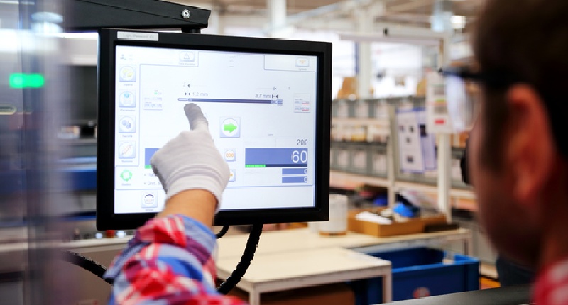
CNC machine tools, laser cutters included, require some initial designing and programming, but once completed, the machines run accurately and repeatedly with minimal interaction with an operator. Programming the machine typically requires basic knowledge of g-code, the machine language used in CNC programming.

However, designing the part requires computer software capable of producing a scalable vector file (SVG). The vector file processes and stores graphics information, which the laserĀ engraving machine uses to generate a G-code program. Although there are various ways of producing a vector file, here is our list of the best and most popular. Most of these come with tutorials to help you get up and running.

LaserGRBL

LaserGRBL is free laser cutter software for Windows, and itā€™s one of the few software programs designed for beginners and hobbyists. With it, almost anyone can learn the basics of control software, file formats, and the ins and outs of laser cuts.

Some of LaserGRBLā€™s valuable features include a jogging feature allowing the operator to manually position the laser head with two sliders, controlling the size and speed of the steps. An override function also allows for speeding up or slowing down the engraving speed and laser power in real time during engraving.

The raster image import function lets you load any image, including photos, clip art, pencil drawings, and icons, intoĀ LaserGRBLĀ and turn it into g-code without additional software. Raster images provide a different type of graphics than the vectors in most laser engraving software.

You can scale vectors up and down and still maintain quality. Still, raster graphics are made up of tiny pixels and are used for cutting and engraving larger areas, meaning GRBL laser cutter software is effective for numerous laser cutting projects.

Unfortunately, recent versions of LaserGRBL are not available for macOS.

Inkscape

A versatile piece of open-source vector graphic software, Inkscape is more of a generalistā€™s tool than a specialist laser cutting software. This free engraver software uses scalable vector graphics (SVG) and can work on PDF, JPG, GIF, and PNG. Unlike LaserGRBL, Inkscape is available on all major desktop platforms, including Mac, Windows, and Linux.

Adobe Illustrator

A graphic design suite? For a laser cutter? It may not make sense initially, but Illustrator has so many features that even SVG files for laser cutters are well within its grasp. While itā€™s not a formal AutoCAD program, Adobe has been the cream of the design software crop for years with Photoshop. That expertise shows through features such as artboards, allowing users to visualize their designs on different materials. Adobe Illustrator isnā€™t free, but for subscribers, such as hobbyists who like to focus more on the design side, it provides all the tools youā€™ll need. Illustrator speeds up many processes, and more tutorials and plug-ins are available to help you become even more productive.

SolveSpace

Unlike Adobe Illustrator, SolveSpace has a relatively simple userĀ interface but a steep learning curve because of its minimal input. Still, SolveSpace can meet your laser-cutting design needs and has some advantages: SolveSpace is extremely resource-friendly, taking up less than 10 MB on your computer. You can run it on an older desktop or laptop without problems, and the program is free. It also exports directly to SVG.

LaserWeb4

LW4 is a free laser cutter program with a community of users to assist with tips, modifications, and additions to the code. The program has various features, including some not found on most other applications. LaserWeb 4 includes materials and price calculators, allowing users to design a new part and estimate how much it will cost. The combination of features plus a supportive community makes LaserWeb 4 an excellent choice for hobbyists or beginners who want to master the complexities of laser cutting.

Coreldraw

CorelDRAW is a popular vector graphics program with all the standard features to make your creations come alive. It offers an intuitive interface with simple tools and competent organization so you can easily see what to do. The latest version even supports PDF/X-4, which means CorelDRAW can save in any format needed for print or web use.

Pressure, angle, and shape are essential to a drawing. If youā€™re looking for the best computer software that can create custom illustrations from scratch with pressure sensitivity in seconds, then look no further than CorelDRAW.

LightBurn

LightBurn is another paid product justifying its monthly subscription with many helpful features, including design and layout features and advanced operations tools. Users can specify the number of passes the cutter takes, depth of cut, cut order, etc. Operators can shortcut the normal process by using LightBurn to talk directly to your laser cutterā€™s control unit, making programming one step instead of two. Although LightBurn doesnā€™t work with every controller available, it is compatible with most, and support is constantly expanding. You can create new vector shapes using the offsetting, welding, and node editing features in LightBurn.

Draft Sight

Draft Sight is professional-grade design software at a relatively high price. Its features include converting JPG files into designs, importing multiple files into a single project, and rendering projects in a wide array of vector and raster image output files, including SVG, EPS, PNG, BMP, DWG, and DXF files. The image conversion feature enables professional designers to reprocess old designs from paper, creating new laser-cutting programs for old designs.

SolidWorks

SolidWorks focuses on converting 3D designs into 2D cutting programs, so although it might not have as many features as most of the other programs on the list, it can quickly render 3D models into linear shapes. SolidWorks offers trials, so try it for architectural-type products and product design.

TurboCAD DesignerĀ 

TurboCAD is a paid, powerful design tool for making the 2D designs required for laser cutting or engraving applications. It exports vector files in DXF, DWG, DWF, and PDF format, which many laser control software accept, and itā€™s also compatible with other file types such as JPG, BMP, ASM, PNG, and more.

TurboCAD Designer runs on Windows and Mac OS, and although youā€™ll need internet access for the initial authentication and updates, you can use it offline. It has lots of features to make laser cutting easy. For example, an Overkill tool removes overlapping arcs and lines within a design, cleaning up a vector drawing for effective laser cutting. You can also use their PDF Insert/Underlay tool, which allows you to copy and save a design as a vector PDF file and trace over it within a new TurboCAD project.

Affinity Designer

Affinity Designer is a vector graphics editor considered one of the best alternatives to Adobe Illustrator. It offers several powerful creation features and tools, including the possibility of working with many artboards at a time and applying custom grids and guides to them. It also enables users to work with raster images, providing enough control for laser engraving.

Affinity Designer software is a one-time purchase available for Windows and Mac or on iPad at a lower price but with most of the primary functions.

Conclusion
Choose between these five free and six paid choices to find the perfect software for your laser cutting machine. Like any CNC machine, thereā€™s a bit of a learning curve. However, with some of the best laser engraving software at your fingertips, youā€™ll soon master the finer points of raster and vector files and design laser engravings confidently.

Looking for a Vertical Milling Machine? Check out the CNC Max

max cnc milling machine
The CNC Max Milling Machine

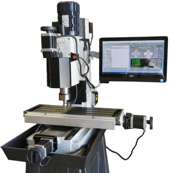
CNC Masters added the CNC MAX to our lineup ofĀ quality CNC mills. Specifically designed for the machinist considering theĀ CNC Baron Mill, the MAX has higher spindle speeds and more Y-axis travel. The value and small footprint of the CNC Baron Mill are enhanced with additional features of the CNC MAX.

Easy to learn and operate, the CNC MAX Milling Machine has a durable cast iron body, just like the CNC Baron. Itā€™s ideal for those demanding users accustomed to machining on classic Bridgeport-type vertical knee milling machines that take up floor space. The MAX provides advanced features that emphasize cutting precision and ease of use. Best of all, itā€™s made in the USA!

Be sure to check out our full listing ofĀ vertical milling machines.

About Peter Jacobs

Peter Jacobs is the Senior Director of Marketing at CNC Masters, a leading supplier of CNC mills, milling machines, and CNC lathes. He is actively involved in manufacturing processes and regularly contributes his insights for various blogs in CNC machining, 3D printing, rapid tooling, injection molding, metal casting, and manufacturing in general. You can connect with him on his LinkedIn.

Have Questions? Need a Quote?

Looking for more information about our CNC machines and services? Contact us today.

Contact

Slide 1

29. Create a Peck Drilling Program in Circular or Rectangular Patterns
Using the Circular or Rectangular Drilling Wizards, you can program the machine to drill an un-limited series of holes along the X and Y planes. Program it to drill straight through to your total depth, use a high-speed pecking cycle, or deep hole pecking cycle. You can program the cut-in depth and return point for a controlled peck drill application to maximize chip clearance.

Slide 1

20. Change up to 30 tools with compensation, and store your tool offsets for other programs
The MX supports…

Slide 1

21. Use the optional ATC rack up to 8 tools for milling, drilling, and rigid tapping applications
The CNC Masters Automatic Tool Changer Rack and Tools (US Patent 9,827,640B2) can be added to any CNC Masters Milling Machine built with the rigid tapping encoder option. The tutorial will guide you through the set-up procedure using the ATC tools.

Slide 1

22. Use the optional Rigid Tapping Wizard without the need for tapping head attachments
When you order your CNC Masters machine, have it built with the optional rigid tapping encoder. You can take any drill cycle program and replace the top line with a tapping code created by the wizard to tap your series of holes up to 1/2ā€ in diameter.

Slide 1

23. Use the optional Digital Probe to scan the profile and/or pockets of your fun/hobby type designs to write your tool path program and machine out a duplicate of your original design To ā€œsurfaceā€ scan an object, you can program the probe along the X or Y plane. The stylus will travel over the part starting on the left side front corner of the object and work its way to the end of the part on the right side. Depending on how the stylus moves, it will record linear and interpolated movements along the X, Y, and Z planes directly on the MX Editor.
To ā€œpocketā€ scan an object containing a closed pocket such as circles or squares, the scan will start from the top front, work its way inside of the pocket, and scan the entire perimeter of the pocket.
Under the Setup of the MX software you will find the Probe Tab which will allow you to calibrate and program your probe. Your ā€œProbe Stepā€, ā€œFeedā€, and ā€œData Filterā€ can also be changed on the fly while the probe is in the middle of scanning your object.

Slide 1

24. Use work offsets G54-G59 for nesting applications
The work offsets offer you a way to program up to six different machining locations. Itā€™s like having multiple 0.0 locations for different parts. This is very useful especially when using sub-routines/nesting applications.

Slide 1

25. Create a Rectangular Pocket / Slot with our selection of Wizards to help you build a tool path program
The Cycle Wizards for the mill or lathe makes it easy to create a simple tool path without needing to use a CAD and CAM software.
On this Wizard, the Rectangular Pocket / Slots, can be used to form a deep rectangular pocket into your material or machine a slot duplicating as many passes needed to its total depth.

Slide 1

26. Create a Circular Pocket Wizard
Input the total diameter, the step down, and total depth and the code will be generated.

Slide 1

27. Do Thread Milling using a single point cutter Wizard

Slide 1

28. Cut a gear out using the Cut Gear Wizard with the optional Fourth Axis

Slide 1

19. Disable the axis motors to manually hand crank each axis into place
Easily de-energize the axis motors by clicking [Disable Motors] to crank each axis by hand, and then press [Reset Control] to re-energize the axis motors.

Slide 1

30. The MX interface can easily be interchanged from Mill Mode to Lathe Mode
Use this interface for your CNC Masters Lathe. It contains all the same user-friendly features and functions that comes in Mill Mode. Simply go to the Setup page and change the interface.

Slide 1

31. Use Tool Change Compensation or the optional Auto Tool Changer Turret if your application requires more than one tool in a single program
You can offset the length and angle of each tool and record it under Tools in your Setup. The program will automatically pause the latheā€™s movement and spindle allowing you to change out your tool, or allowing the optional ATC Turret to quickly turn to its next tool and continue machining.
On the MX interface, you also have four Tool Position buttons. Select your desired T position, and the auto tool post will quickly turn and lock itself to that position.

Slide 1

32. Use the Lathe Wizard Threading Cycle to help you program your latheā€™s internal or external threads in inches or metric

Slide 1

33. Use the Lathe Wizard Turning / Boring Cycle to help you program simple turning and boring cycles without having to go through a CAM or writing a long program with multiple passes

Slide 1

34. Use the Lathe Wizard Peck Drilling Cycle to help you program your drill applications or for face grooving

Slide 1

35. Facing / Grooving / Part Off Cycle Wizards ā€“ with Constant Surface Speed
These cycles can be used with Constant Surface Speed allowing the spindle speed to increase automatically as the diameter of the part decreases giving your application a consistent workpiece finish. With CSS built into the wizard, there is no need to break down the cycle into multiple paths and multiple spindle speed changes.

Slide 1

36. This is our list of supported G and M codes which can be found under Tools > G Code/ M Code List in the MX
If you plan to use a third-party CAM software to generate your tool path program, use a generic FANUC post processor and edit it to match our list of codes. As an option, we also sell Visual mill/turn CAM software which comes with a guaranteed post processor for our machines to easily generate your tool path programs based on your CAD drawings.

Slide 1

37. Our pledge to you…

Slide 1

10. Run each tool path independently to study its movement
1. Run the machine on Trace mode. You can run each tool path independently, one line at a time to study the tool path movement on the machine to verify the position of the application and if any fixture/vise is in the way of the cutterā€™s path.

2. You can also verify your program by clicking on the Trace and Draw buttons together. This will allow you to view each tool path independently one line at a time in the Draw Window.

Slide 1

2. Clutter Free Interface
The MX is engineered for the CNC MASTERS machine so you do not have to fiddle with a detailed complicated configuration that can be overwhelming. Just load in the MX and start machining!2. Clutter Free Interface
The MX is engineered for the CNC MASTERS machine so you do not have to fiddle with a detailed complicated configuration that can be overwhelming. Just load in the MX and start machining!

Slide 1

3. Features Tour and Tutorials Included
The Features Tour will give you a quick run-down on all the features the MX can do for you. The Tutorials are easy to follow even for the first time CNC machinist.
Feel free to download the MX on any of your computers. We recommend downloading the MX along with your CAD and CAM software there at the comfort of your office computer to generate your tool path programs. You donā€™t need to be hooked up to the machine either to test your program in simulation mode.

Slide 1

4. Navigate and Edit Your Program through the MX interface with Ease
With a few clicks of the mouse or using touch screen technology, you can easily navigate through the MX interface importing saved programs into the Editor from the File drop down menu. Using standard windows features to edit your program you can then lock the Editor Screen to avoid accidental editing, and if you need to insert a line in the middle of a program, just click on [ReNum] to re-number your tool path list.
You can create a program or import CAM generated G-code tool paths into the Editor
The X Y and Z W arrow jog buttons are displayed from the point of view of the cutter to avoid confusion when the table and saddle are moving. You can also adjust your spindle speed and coolant control while jogging each axis.

Slide 1

5. Feed Hold ā€“ Pause in the Middle of your Program
Feed Hold lets you pause in the middle of a program. From there you can step through your program one line at time while opting to shut the spindle off and then resume your program.
You can also write PAUSE in the middle of your program and jog each axis independently while your program is in pause mode.

Slide 1

6. Hot Keys
Hot Keys is an alternative method to easily control your machine using your hard or touch screen keyboard. One can press P to pause a program, press S to turn Spindle On, G to run a program, Space Bar to Stop, J to record your individual movements one line at a time to create a program in teach mode.

Slide 1

7. Pick Menu ā€“ for conversational mode programming
Write FANUC style G-codes directly into the Editor or select commands off the [Pick] menu and write your tool path program in conversational mode such as what is written in the Editor box. You can even mix between conversation commands and G-codes in the same program.

Slide 1

8. Pick Menu List of Options
Use commands such as MOVE, SPINDLE ON/OFF, COOLANT ON/OFF, PAUSE, DELAY, GO HOMEā€¦. to write your tool path programs in conversational mode.

Slide 1

9. Draw the Tool Path to verify it before pressing Go
Hit Draw to view your tool path program drawing, check out its run time, or even simulate the tool path in 3D mode. This can be helpful to quickly verify your program before running it. You can also slow down or speed up the drawing or simulation process.
You can also hit Go within the Draw Window itself to verify the cutterā€™s position on the machine. The current tool path will be highlighted and simultaneously draw out the next path so you can verify what the cutter will be doing next on the program.

Slide 1

MX Software ā€“ Easy to Use, Easy to Learn ā€“ Included with your machine purchase
The MX software is designed to work seamlessly with your CNC Masters machine. It is made to work with Windows PC ā€“ desktop, laptop, or an all in one ā€“ on standard USB. Use it on Windows 8 or 10 64-bit operating systems.
No internal conversion printer/serial port to USB software or additional conversion hardware is used with the MX.

Slide 1

11. Counters display in Inches or Millimeters ā€“ Continuous Feed
1. When running a program, the counters will display a ā€œreal-timeā€ readout while the machine is in CNC operation without counting ahead of the movement.
2. The current tool path is highlighted while the machine is in operation without causing slight interruptions/pauses as the software feeds the tool path to the machine. The MX internally interprets a program ten lines ahead to allow for ā€œcontinuous machiningā€ avoiding slight interruptions as the machine waits for its next tool path command.
3. ā€œRun Timeā€ tells you how long it takes to run your tool path program.

Slide 1

12. Use the ā€œGo From Lineā€ command to start in the middle of your program
If you ever need to begin your program from somewhere in the middle of it, use [Go From Line] which you can find under Tools. The Help guide will walk you through how to position the cutter without losing its position on the machine.

Slide 1

13. Exact Motion Distance without over-stepping on an axis while jogging
Use ā€œRelative ONā€ to enter a specific coordinate to jog any of your axes to an exact location without having to write a program. Itā€™s like using ā€œpower feedā€ but easier. You can jog an exact distance on any of the axes without needing to keep the key pressed down and mistakenly over-step the movement releasing your finger too slowly off the jog button.
Letā€™s say you need to drill a hole exactly 0.525ā€ using the Z. So you enter 0.525 in the Z box. Next, adjust the JOG FEED RATE slider for the desired feed rate. Then ā€œclick onceā€ on the +Z or -Z button to activate the travel. In this case you click once the -Z button first to drill the hole exactly 0.525ā€. Then click once on the +Z button to drive the axis back up 0.525ā€.

Slide 1

14. Teach Mode ā€“ Jog Input
You can create a tool path program by storing each point-to-point movement by simply jogging an axis one at a time. Click on either of the Jog Input buttons to store each movement on the Editor Screen. You can then add Spindle ON, feed commands, and press GO to run the new program as needed. This is a great feature to help you learn to create a program by the movements you make on the machine without necessarily writing out an entire program first.

Slide 1

15. Override on the fly to adjust the Jog Feed to Rapid or the Spindle Speed during the middle of a program
1. Jog Feed and Rapid with Override: You can adjust feeds using the slider from slow minimum 0.1ā€³ per minute to a rapid of 100ā€³ per minute of travel. You can even micro-step your jog as low as 0.01ā€/min. The [-][+] buttons allow you to fine tune feeds in 5% increments while the program is in motion.
2. Spindle Speed with Override: You can adjust speeds using the slider from a slow minimum RPM to the max RPM according to the machine setup. The [-][+] buttons allow you to fine tune feeds in 5% increments while the program is in motion.

Slide 1

16. Adjust Counters using Pre-Set if you cannot begin the program from 0.00
In a situation where you cannot begin your cutter at itā€™s 0.00 location, you can ā€œPre-Setā€ directly into the counters by typing in your beginning coordinate. You can press Go from here to run your program. You can also ā€œzero allā€ or ā€œzeroā€ your counters independently. With one click of the [Return to 0.0] button, all axes will travel back to its respective 0.0 on the machine.

Slide 1

17. Set and Save your 0.00 position for future runs
Set and save your 0.00 position on the machine. These coordinates will be recorded as the first line of the program in the Editor Screen. Should you desire to return to this program at a later date, you only have to click on the Set Zero Return button. This will command the machine to automatically jog each axis to its saved ā€œsetā€ 0.00 position according to the recorded coordinates at the first line of the program.

Slide 1

18. Create a ā€œHomeā€ position to clear your application and run multiple times
Letā€™s say you need to machine one application times 100 pieces. This usually requires a jig to retain that physical 0.00 position. But in this case, you want the program to end with a clearance of the axes to easily switch out the next piece of stock and start again. With Save Home, you have the ability to save this offset (home) position while still retaining your Set Zero position where the machine will mill your part out. Pressing [Save Home] will record this new position under the Set Zero line in your program.
Pressing [Go Home] will jog your axes back to your ā€œsaved homeā€ position where you originally pressed the Save Home command. You can also input GO_HOME from the Pick Menu as its own tool path in your program. At the completion of your program the axes will end at your Home position. Replace your part, then press [Return to 0.0] button to allow the axes to return to its zero position, and press Go to start your next run.

previous arrow
next arrow