CALL US TODAY

CALL US TODAY

sheet of aluminum being cut

How To Cut Aluminum Sheets and Plates

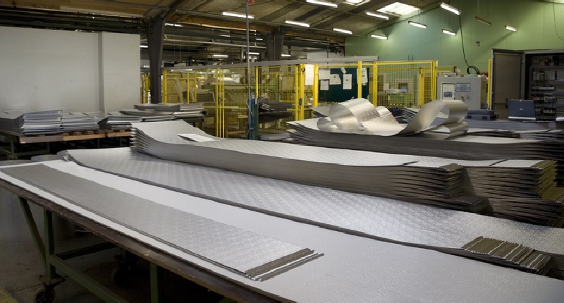
Aluminum is among the most versatile and widely used metals worldwide in DIY workshops and metalworking facilities. Despite being easily machinable, aluminum does pose some challenges. Because aluminum is typically easy to work with, some beginners have trouble holding their cut lines. Aluminum is soft, has a low melting point, and can warp or bend if not cut properly. At best, that leaves the machinist with more work. In the worst case, it can ruin an otherwise good project. Thatā€™s why having the right blade, tools, and procedures is essential to make the perfect cut every time.

The Best Tools To Cut Aluminum Sheets and Pieces

Metal Shears

Metal shears, or tin snips, are the most common tools for cutting aluminum. Many aluminum projects are small, quick jobs that need some fast trimming. Shears are perfect in that situation. They donā€™t heat the metal, they can be maneuvered into tight spots for hard-to-reach cuts, and thereā€™s no power requirement, so you can take them anywhere to cut almost anything.

Circular Saw

Circular saws are easy to use and widely available. They work well for straight cuts on sheet metal, but they work best with special sheet metal cutting blades. Circular saws arenā€™t the best choice for thicker sections but are ideal for quick cuts and smaller areas. Circular saws and miter saws are excellent choices for precise cuts on aluminum, especially in preparation for more detailed work.
circular saw aluminum
Table Saw

With a built-in edge guide, table saws can cut a straight edge on sheet metal, including aluminum. Follow the same advice for a circular saw and use a dedicated non-ferrous metal cutting saw blade.

Jigsaw

Table and circular saws are best for straight, smooth cuts. Jig, reciprocal, and handheld circular saws can cut curves and shapes in ways that table saws cannot. Bandsaws are also an option, but they donā€™t offer the same security and power as other options, relying more on the operatorā€™s skill to keep the saw steady and produce a clean cut.

Metal Brake

Metal brakes are special metal-cutting machines that use a slightly different approach. Unlike power tools, metal brakes use a bending action to flex and score the metal, causing it to break cleanly along a straight line. Metal brakes are large and can be cumbersome, but theyā€™re one of the best options for cutting long, straight sections of aluminum sheet metal.

Hacksaw

A hacksaw is a handy tool for cutting a smaller piece of aluminum. You can use it to cut pipe and bar, but itā€™s also effective when you need a shorter length of sheet aluminum. Fortunately, there are other blades available if those do not work out or if they wear down quickly over time.

Chopsaw

Also known as a cut-off saw, a chop saw is a great option for cutting aluminum because it makes straight, precise cuts fast, especially when equipped with a blade designed for non-ferrous metals.

CNC Machine

The abovementioned methods work best when cutting aluminum sheet metal or bar stock into more manageable pieces. High-speed CNC machine tools provide some of the best options for more detailed work. CNC lathes and mills turn thick aluminum pieces into finished parts and can be used to create entire production runs of identical parts.

Plasma Cutter

Plasma cutting is a melting process in which a jet of ionized gas at temperatures above 20,000Ā°C is used to melt and force material from the cut. An electric arc is struck between an electrode and the workpiece. The electrode is recessed in a gas nozzle that constricts the arc, causing the narrow, high-temperature, high-velocity plasma jet to form. Plasma arc cutting works on electrically conductive alloys, including plain carbon and stainless steels, aluminum, nickel alloys, and titanium.

Router

Another way to cut an aluminum pipe is with a router. A router table is a safe option, but if you donā€™t have one, a hand-held router will do the job, too.

Aluminum Cutting Process: Tips and Tricks

When cutting aluminum, remember these tips for making your job a lot easier.

Woodworking tools will work

Since aluminum is one of the softer metals, you can repurpose some of your high-quality wood-cutting tools to cut aluminum as well. Make sure to always use a carbide-tipped blade.

Use lubricant

Metal-cutting lubricants help to reduce chatter and inconsistencies during the cut and can also help to remove swarf and chips. The most common lubricant for aluminum is WD-40, but others, such as metal cutting wax and water, work equally well in preventing blades from clogging.

Smaller diameter blades are better

Typically, smaller diameter blades produce cleaner, more accurate cuts because their smaller diameter results in less runout, and less runout means a smoother cut.

clamping when cutting aluminum
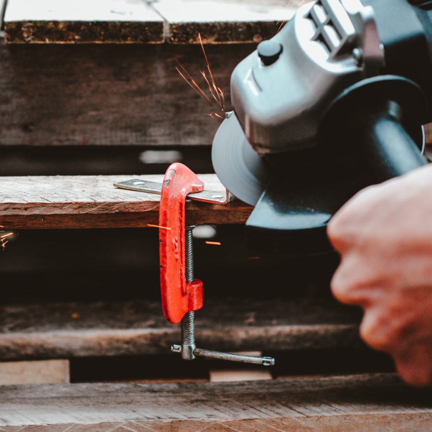
Clamp your workpiece

Clamping your workpiece gives it stability, and a stable workpiece allows for a cleaner cut. Another benefit of clamping is it improves safety with less chance of something flying off the saw and harming the operator.

Wear protection

Always wear adequate protective equipment when cutting aluminum or any other material, including safety glasses or safety goggles, and hearing protection. Full-face shields might also be advisable.

Use The Correct Hand Tools

Tin snips and shears, angle grinders, chisels, and carbide blades are all craftsmanā€™s tools for tackling professional or DIY projects. Either way, have the correct hand tools to complement your saws or machine tools. Cutting thick aluminum pipes might require a carbide-tipped metal cutting circular saw blade. Most of these tools are available at retailers such as Amazon.

4 Simple Steps to Cut Aluminum With a Circular Saw

Ready for the simple process? Follow these steps to cut aluminum sheet metal or bar stock.

Set It Up Correctly

Circular saws require clearance beneath the workpiece. If youā€™re clamping your aluminum sheet to a sawhorse, be sure youā€™ve got enough support to cut close to the stand without cutting into it. A good setup also requires considering how large the blade is, where it will travel, and if itā€™s thick enough to offer a clean cut.

Lay Out and Measure Your Cut

If youā€™re using a CNC machine, you must program the machine with the exact cuts in the operation. If youā€™re cutting off bar stock, a simple layout line or tape measure will suffice. Aluminum sheets should be laid out so you have something to follow as you cut.

Lubricate The Blade

Use WD-40, water, or cutting wax to lubricate your blade to prevent clogging. A lubricant reduces friction, makes a cleaner cut, and keeps the blade and workpiece from overheating. Keep your blade perpendicular to the workpiece. Angled cuts are thicker since there is more material, leading to distorted or warped cuts and jagged and uneven edges.

Clamp The Workpiece

High-quality, cast-iron C-clamps are a great way to secure your aluminum workpiece. Use more than one clamp along the path of the bladeā€™s travel so that the workpiece doesnā€™t move from the blade during cutting.

Looking for even more ways to cut aluminum? This video includes a few that arenā€™t on this list, so feel free to check it out.

About Peter Jacobs

Peter Jacobs is the Senior Director of Marketing at CNC Masters, a leading supplier of CNC mills, milling machines, and CNC lathes. He is actively involved in manufacturing processes and regularly contributes his insights for various blogs in CNC machining, 3D printing, rapid tooling, injection molding, metal casting, and manufacturing in general. You can connect with him on his LinkedIn.

Have Questions? Need a Quote?

Looking for more information about our CNC machines and services? Contact us today.

Contact

Slide 1

29. Create a Peck Drilling Program in Circular or Rectangular Patterns
Using the Circular or Rectangular Drilling Wizards, you can program the machine to drill an un-limited series of holes along the X and Y planes. Program it to drill straight through to your total depth, use a high-speed pecking cycle, or deep hole pecking cycle. You can program the cut-in depth and return point for a controlled peck drill application to maximize chip clearance.

Slide 1

20. Change up to 30 tools with compensation, and store your tool offsets for other programs
The MX supports…

Slide 1

21. Use the optional ATC rack up to 8 tools for milling, drilling, and rigid tapping applications
The CNC Masters Automatic Tool Changer Rack and Tools (US Patent 9,827,640B2) can be added to any CNC Masters Milling Machine built with the rigid tapping encoder option. The tutorial will guide you through the set-up procedure using the ATC tools.

Slide 1

22. Use the optional Rigid Tapping Wizard without the need for tapping head attachments
When you order your CNC Masters machine, have it built with the optional rigid tapping encoder. You can take any drill cycle program and replace the top line with a tapping code created by the wizard to tap your series of holes up to 1/2ā€ in diameter.

Slide 1

23. Use the optional Digital Probe to scan the profile and/or pockets of your fun/hobby type designs to write your tool path program and machine out a duplicate of your original design To ā€œsurfaceā€ scan an object, you can program the probe along the X or Y plane. The stylus will travel over the part starting on the left side front corner of the object and work its way to the end of the part on the right side. Depending on how the stylus moves, it will record linear and interpolated movements along the X, Y, and Z planes directly on the MX Editor.
To ā€œpocketā€ scan an object containing a closed pocket such as circles or squares, the scan will start from the top front, work its way inside of the pocket, and scan the entire perimeter of the pocket.
Under the Setup of the MX software you will find the Probe Tab which will allow you to calibrate and program your probe. Your ā€œProbe Stepā€, ā€œFeedā€, and ā€œData Filterā€ can also be changed on the fly while the probe is in the middle of scanning your object.

Slide 1

24. Use work offsets G54-G59 for nesting applications
The work offsets offer you a way to program up to six different machining locations. Itā€™s like having multiple 0.0 locations for different parts. This is very useful especially when using sub-routines/nesting applications.

Slide 1

25. Create a Rectangular Pocket / Slot with our selection of Wizards to help you build a tool path program
The Cycle Wizards for the mill or lathe makes it easy to create a simple tool path without needing to use a CAD and CAM software.
On this Wizard, the Rectangular Pocket / Slots, can be used to form a deep rectangular pocket into your material or machine a slot duplicating as many passes needed to its total depth.

Slide 1

26. Create a Circular Pocket Wizard
Input the total diameter, the step down, and total depth and the code will be generated.

Slide 1

27. Do Thread Milling using a single point cutter Wizard

Slide 1

28. Cut a gear out using the Cut Gear Wizard with the optional Fourth Axis

Slide 1

19. Disable the axis motors to manually hand crank each axis into place
Easily de-energize the axis motors by clicking [Disable Motors] to crank each axis by hand, and then press [Reset Control] to re-energize the axis motors.

Slide 1

30. The MX interface can easily be interchanged from Mill Mode to Lathe Mode
Use this interface for your CNC Masters Lathe. It contains all the same user-friendly features and functions that comes in Mill Mode. Simply go to the Setup page and change the interface.

Slide 1

31. Use Tool Change Compensation or the optional Auto Tool Changer Turret if your application requires more than one tool in a single program
You can offset the length and angle of each tool and record it under Tools in your Setup. The program will automatically pause the latheā€™s movement and spindle allowing you to change out your tool, or allowing the optional ATC Turret to quickly turn to its next tool and continue machining.
On the MX interface, you also have four Tool Position buttons. Select your desired T position, and the auto tool post will quickly turn and lock itself to that position.

Slide 1

32. Use the Lathe Wizard Threading Cycle to help you program your latheā€™s internal or external threads in inches or metric

Slide 1

33. Use the Lathe Wizard Turning / Boring Cycle to help you program simple turning and boring cycles without having to go through a CAM or writing a long program with multiple passes

Slide 1

34. Use the Lathe Wizard Peck Drilling Cycle to help you program your drill applications or for face grooving

Slide 1

35. Facing / Grooving / Part Off Cycle Wizards ā€“ with Constant Surface Speed
These cycles can be used with Constant Surface Speed allowing the spindle speed to increase automatically as the diameter of the part decreases giving your application a consistent workpiece finish. With CSS built into the wizard, there is no need to break down the cycle into multiple paths and multiple spindle speed changes.

Slide 1

36. This is our list of supported G and M codes which can be found under Tools > G Code/ M Code List in the MX
If you plan to use a third-party CAM software to generate your tool path program, use a generic FANUC post processor and edit it to match our list of codes. As an option, we also sell Visual mill/turn CAM software which comes with a guaranteed post processor for our machines to easily generate your tool path programs based on your CAD drawings.

Slide 1

37. Our pledge to you…

Slide 1

10. Run each tool path independently to study its movement
1. Run the machine on Trace mode. You can run each tool path independently, one line at a time to study the tool path movement on the machine to verify the position of the application and if any fixture/vise is in the way of the cutterā€™s path.

2. You can also verify your program by clicking on the Trace and Draw buttons together. This will allow you to view each tool path independently one line at a time in the Draw Window.

Slide 1

2. Clutter Free Interface
The MX is engineered for the CNC MASTERS machine so you do not have to fiddle with a detailed complicated configuration that can be overwhelming. Just load in the MX and start machining!2. Clutter Free Interface
The MX is engineered for the CNC MASTERS machine so you do not have to fiddle with a detailed complicated configuration that can be overwhelming. Just load in the MX and start machining!

Slide 1

3. Features Tour and Tutorials Included
The Features Tour will give you a quick run-down on all the features the MX can do for you. The Tutorials are easy to follow even for the first time CNC machinist.
Feel free to download the MX on any of your computers. We recommend downloading the MX along with your CAD and CAM software there at the comfort of your office computer to generate your tool path programs. You donā€™t need to be hooked up to the machine either to test your program in simulation mode.

Slide 1

4. Navigate and Edit Your Program through the MX interface with Ease
With a few clicks of the mouse or using touch screen technology, you can easily navigate through the MX interface importing saved programs into the Editor from the File drop down menu. Using standard windows features to edit your program you can then lock the Editor Screen to avoid accidental editing, and if you need to insert a line in the middle of a program, just click on [ReNum] to re-number your tool path list.
You can create a program or import CAM generated G-code tool paths into the Editor
The X Y and Z W arrow jog buttons are displayed from the point of view of the cutter to avoid confusion when the table and saddle are moving. You can also adjust your spindle speed and coolant control while jogging each axis.

Slide 1

5. Feed Hold ā€“ Pause in the Middle of your Program
Feed Hold lets you pause in the middle of a program. From there you can step through your program one line at time while opting to shut the spindle off and then resume your program.
You can also write PAUSE in the middle of your program and jog each axis independently while your program is in pause mode.

Slide 1

6. Hot Keys
Hot Keys is an alternative method to easily control your machine using your hard or touch screen keyboard. One can press P to pause a program, press S to turn Spindle On, G to run a program, Space Bar to Stop, J to record your individual movements one line at a time to create a program in teach mode.

Slide 1

7. Pick Menu ā€“ for conversational mode programming
Write FANUC style G-codes directly into the Editor or select commands off the [Pick] menu and write your tool path program in conversational mode such as what is written in the Editor box. You can even mix between conversation commands and G-codes in the same program.

Slide 1

8. Pick Menu List of Options
Use commands such as MOVE, SPINDLE ON/OFF, COOLANT ON/OFF, PAUSE, DELAY, GO HOMEā€¦. to write your tool path programs in conversational mode.

Slide 1

9. Draw the Tool Path to verify it before pressing Go
Hit Draw to view your tool path program drawing, check out its run time, or even simulate the tool path in 3D mode. This can be helpful to quickly verify your program before running it. You can also slow down or speed up the drawing or simulation process.
You can also hit Go within the Draw Window itself to verify the cutterā€™s position on the machine. The current tool path will be highlighted and simultaneously draw out the next path so you can verify what the cutter will be doing next on the program.

Slide 1

MX Software ā€“ Easy to Use, Easy to Learn ā€“ Included with your machine purchase
The MX software is designed to work seamlessly with your CNC Masters machine. It is made to work with Windows PC ā€“ desktop, laptop, or an all in one ā€“ on standard USB. Use it on Windows 8 or 10 64-bit operating systems.
No internal conversion printer/serial port to USB software or additional conversion hardware is used with the MX.

Slide 1

11. Counters display in Inches or Millimeters ā€“ Continuous Feed
1. When running a program, the counters will display a ā€œreal-timeā€ readout while the machine is in CNC operation without counting ahead of the movement.
2. The current tool path is highlighted while the machine is in operation without causing slight interruptions/pauses as the software feeds the tool path to the machine. The MX internally interprets a program ten lines ahead to allow for ā€œcontinuous machiningā€ avoiding slight interruptions as the machine waits for its next tool path command.
3. ā€œRun Timeā€ tells you how long it takes to run your tool path program.

Slide 1

12. Use the ā€œGo From Lineā€ command to start in the middle of your program
If you ever need to begin your program from somewhere in the middle of it, use [Go From Line] which you can find under Tools. The Help guide will walk you through how to position the cutter without losing its position on the machine.

Slide 1

13. Exact Motion Distance without over-stepping on an axis while jogging
Use ā€œRelative ONā€ to enter a specific coordinate to jog any of your axes to an exact location without having to write a program. Itā€™s like using ā€œpower feedā€ but easier. You can jog an exact distance on any of the axes without needing to keep the key pressed down and mistakenly over-step the movement releasing your finger too slowly off the jog button.
Letā€™s say you need to drill a hole exactly 0.525ā€ using the Z. So you enter 0.525 in the Z box. Next, adjust the JOG FEED RATE slider for the desired feed rate. Then ā€œclick onceā€ on the +Z or -Z button to activate the travel. In this case you click once the -Z button first to drill the hole exactly 0.525ā€. Then click once on the +Z button to drive the axis back up 0.525ā€.

Slide 1

14. Teach Mode ā€“ Jog Input
You can create a tool path program by storing each point-to-point movement by simply jogging an axis one at a time. Click on either of the Jog Input buttons to store each movement on the Editor Screen. You can then add Spindle ON, feed commands, and press GO to run the new program as needed. This is a great feature to help you learn to create a program by the movements you make on the machine without necessarily writing out an entire program first.

Slide 1

15. Override on the fly to adjust the Jog Feed to Rapid or the Spindle Speed during the middle of a program
1. Jog Feed and Rapid with Override: You can adjust feeds using the slider from slow minimum 0.1ā€³ per minute to a rapid of 100ā€³ per minute of travel. You can even micro-step your jog as low as 0.01ā€/min. The [-][+] buttons allow you to fine tune feeds in 5% increments while the program is in motion.
2. Spindle Speed with Override: You can adjust speeds using the slider from a slow minimum RPM to the max RPM according to the machine setup. The [-][+] buttons allow you to fine tune feeds in 5% increments while the program is in motion.

Slide 1

16. Adjust Counters using Pre-Set if you cannot begin the program from 0.00
In a situation where you cannot begin your cutter at itā€™s 0.00 location, you can ā€œPre-Setā€ directly into the counters by typing in your beginning coordinate. You can press Go from here to run your program. You can also ā€œzero allā€ or ā€œzeroā€ your counters independently. With one click of the [Return to 0.0] button, all axes will travel back to its respective 0.0 on the machine.

Slide 1

17. Set and Save your 0.00 position for future runs
Set and save your 0.00 position on the machine. These coordinates will be recorded as the first line of the program in the Editor Screen. Should you desire to return to this program at a later date, you only have to click on the Set Zero Return button. This will command the machine to automatically jog each axis to its saved ā€œsetā€ 0.00 position according to the recorded coordinates at the first line of the program.

Slide 1

18. Create a ā€œHomeā€ position to clear your application and run multiple times
Letā€™s say you need to machine one application times 100 pieces. This usually requires a jig to retain that physical 0.00 position. But in this case, you want the program to end with a clearance of the axes to easily switch out the next piece of stock and start again. With Save Home, you have the ability to save this offset (home) position while still retaining your Set Zero position where the machine will mill your part out. Pressing [Save Home] will record this new position under the Set Zero line in your program.
Pressing [Go Home] will jog your axes back to your ā€œsaved homeā€ position where you originally pressed the Save Home command. You can also input GO_HOME from the Pick Menu as its own tool path in your program. At the completion of your program the axes will end at your Home position. Replace your part, then press [Return to 0.0] button to allow the axes to return to its zero position, and press Go to start your next run.

previous arrow
next arrow