CALL US TODAY

CALL US TODAY

bench drill press

What To Look For In Your Next Drill Press

Drilling holes with your cordless drill might have worked fine on your latest small DIY project. But sooner or later, youā€™ll want to tackle a home improvement requiring holes at specific depths and distances, and youā€™ll realize that the hand-held power tool isnā€™t up for the task.

Cordless drills have many uses, but precision drilling isnā€™t one of them. Once you understand youā€™ll need the increased accuracy that only a drill press can provide, you have to decide which features youā€™ll need and how much youā€™re willing to pay for them.

This buyerā€™s guide is designed to help you choose a drill press that will give you excellent results in your next project. DIYers need the right drill pressā€™s versatility to successfully complete a wide range of metalworking and woodworking projects.

Ready to step up to a sturdy, efficient, and powerful tool? Hereā€™s what you should know to find the perfect drill press for you.

What are the common uses of drill presses?

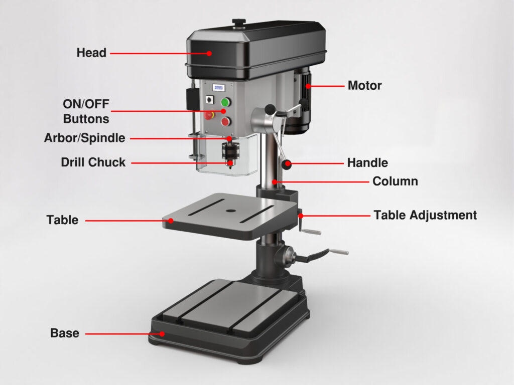
A drill press has a drill chuck that holds the drill bits for drilling holes of various diameters. But thatā€™s where the similarities to hand-held drills end since drill presses are not hand-power tools. The drill pressā€™s headā€”consisting of a motor, chuck assembly, speed control handle, and feed handleā€”is set on top of a heavy-duty support column and base. An adjustable drill press table rides along the column and can support a vise.

The support offered to the head assembly, and chuck by the cast iron base and column prevents any movement of the workpiece during drilling, eliminating most quality issues. Woodworkers, machinists, and hobbyists favor the drill press because it offers more power and accuracy, allowing them to drill larger holes and work with tougher materials.

There are many uses for a drill press that go beyond drilling holes straight through a workpiece. Here are a few examples:

  • Drilling holes to a specific depth with the help of a depth stop.
  • Drilling holes at an angle by tilting the head or the table if the drill press has one of these features.
  • Reaming precise holes that require a specific diameter.
  • Creating threaded holes with a tap.
  • Countersinking holes for a flat-headed screw or to deburr a holeā€™s edge.
  • Counterboring to allow for a socket head cap screw.
  • Cutting square or rectangular holes in wood using a mortising bit.
  • As a sander. Some drill presses have oscillating spindles with a sanding drum that fits into the drill chuck.
benchtop drill press diagram
Diagram of a benchtop drill press

What Are the Main Types of Drill Presses?

The several primary types of drill presses, each with specific uses.

Benchtop Drill Press

bench drill press
benchtop drill press

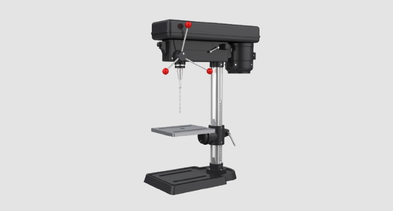
As the name suggests, the benchtop model fits conveniently on a workbench/tabletop and takes up minimum space in a small workshop. These drill presses are best for smaller jobs and typically have an 8- to 12-inch swing. (Swing is the distance from the center of the drill chuck to the edge of the support column, times two). The benchtop drill press can drill 2ā€ to 3-3/8ā€ deep. If youā€™re looking for a compact-size drill press for a garage, these are the best drill press for you.

Floor Drill Press

floor drill press
floor drill press

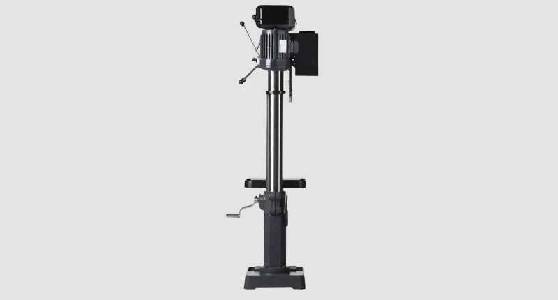
On the other hand, floor drill presses stand alone and are fastened directly to the shop floor. These floor models offer more horsepower for heavy-duty jobs and larger workpieces, typically featuring a 13-to-20-inch swing and drilling capability of 3 to 6 inches deep.

CNC Drill Press

a cnc drill press machine
CNC drill press

Combine the power of a benchtop drill press and the precision of a CNC machine, and you get a CNC drill press. These machines utilize technology and software to make precision drills. Theyā€™re more and more common today in multiple industries because their drills are accurate. There are also mill drills, which combine a milling machine and drill press.

Magnetic Drill Press

magnetic drill press - mag drill
magnetic drill press (mag drill)

A magnetic drill press allows you to attach the drill to any metal base securely. Theyā€™re great for hard-to-reach places on the job site where you need the power of a drill press but need a mobile solution.

What features should I look for in a drill press?

Sufficient Horsepower

What is enough horsepower? As a rule of thumb, you should not settle for less than 1/2 horsepower to ensure you have a powerful motor and adequate speed range. For example, the WEN 4214 has a 5-amp 2/3-horsepower 12-inch drill press. This variable-speed drill press has plenty of power to handle your intense drilling needs. So, there is little reason to spend more on models that offer over one horsepower unless you are drilling large holes in tough metals regularly.

Swing Size

Remember, the swing size is the distance from the center of the chuck to the column times two, so a 12-inch swing means you can drill a hole in the center of a 12ā€ workpiece. If you determine youā€™ll be drilling holes more than six inches from the edge of your workpieces, you will need to look at something larger than a 12-inch drill press.

No Wobble

The point of a drill press vs. a handheld drill is for power and security. The best drill presses wonā€™t wobble when used. If a drill press does move unnecessarily, it might be time for a new one.

Make Sure the Machine Has a Depth Stop

A depth stop is an essential feature if you are going to be drilling several holes at the same depth. For example, if you need to drill 12 holes and all of them must be 2ā€ deep, the depth stop will ensure that all twelve holes will be the same 2ā€ depth.

Get the Most Stroke Distance You Can Afford

Stroke distance is often referred to as quill travel or spindle travel, and it measures the maximum depth a spindle, drill chuck, and drill bit can travel as the operator rotates the feed handle without moving the table up. More stroke distance (3ā€³ to 5ā€³) typically means a higher price, but it also allows for working with longer drill bits and thicker material and adds to the drill pressā€™s versatility.

Digital Readout

A digital readout, sometimes called digital speed readout, on a drill press is a helpful feature that displays the running speed and eliminates guessing your RPMs. Some DROs also measure the depth of the hole youā€™re drilling.

Choose a Drill Chuck With a Large Capacity and a Chuck Key

Drill chucks tightened by hand are convenient and eliminate the possibility of losing the key. Still, if you intend to drill relatively large diameters, itā€™s more secure to tighten the chuck with a wrench or chuck key. Also, a 5/8ā€³ diameter drill chuck is ideal for drilling larger holes.

Get a High-Quality Worktable

Youā€™ll want a table you can adjust up or down depending on the size of the workpiece and the depth of the drilled holes. You can even swivel some of these tables.

Warranty

Make sure a solid warranty backs your drill press. For example, RYOBI offers a 3-year manufacturerā€™s 10ā€³ drill press warranty that includes an EXACTLINE Laser Guide Alignment System.

Common Drill Press Accessories

  • If youā€™re opting for a benchtop drill press, get a heavy-duty worktable on which to attach it.
  • A drill press vise is invaluable for holding smaller parts for drilling.
  • Mortising chisels are used for cutting squares and other shapes.
  • A built-in LED work light provides direct lighting and reduces shadows.
  • Sanding drums for sanding tasks
  • Look for a model with a laser guide that aligns with the drill point using crosshair lines on the workpiece. The laser guide allows for pinpoint drilling

How much does a drill press cost?

Drill presses come with a variety of features and accessories that greatly impact their cost. Smaller benchtop drill presses can start as low as $40 ā€“ $50 and can be found on eBay, Amazon, or your local hardware store.

For larger drill presses with more features like a JET, prices go up to $10,000 and beyond. Just like with a milling machine or router, you can expect to get what you pay for.

Benefits of Owning a Drill Press

Drill presses provide a level of control and power that handheld cordless drills donā€™t. Theyā€™re faster and allow for more accurate drilling, which allows the user to drill more even and uniform holes.

In addition, a solid drill press will allow you to drill through harder surfaces than a handheld. Many drill presses can handle larger drill bits than handheld drills, which makes them more versatile for larger jobs.

Since drilling is a common job, drill presses are used frequently. A good drill press will last longer than a handheld drill while providing consistent performance.

Is a drill press worth the money?

Yes. Most buyers should strongly consider a drill press because of its accuracy and speed.

Specific tools would be on your must-have list if you were to design a machine shop. First of all, itā€™s hard to imagine getting by without a milling machine, lathe, bandsaw, grinder machine, and perhaps a router. However, equally essential to your successful shop is the versatile drill press. Whether itā€™s a Jet floor drill press, a Shop Fox bench top or radial drill press, a powerful magnetic drill, or an entry-level 5-speed drill press from Amazon, youā€™ll turn to your drill press countless times to make it easier to build things.

About Peter Jacobs

Peter Jacobs is the Senior Director of Marketing at CNC Masters, a leading supplier of CNC mills, milling machines, and CNC lathes. He is actively involved in manufacturing processes and regularly contributes his insights for various blogs in CNC machining, 3D printing, rapid tooling, injection molding, metal casting, and manufacturing in general. You can connect with him on his LinkedIn.

Have Questions? Need a Quote?

Looking for more information about our CNC machines and services? Contact us today.

Contact

Slide 1

29. Create a Peck Drilling Program in Circular or Rectangular Patterns
Using the Circular or Rectangular Drilling Wizards, you can program the machine to drill an un-limited series of holes along the X and Y planes. Program it to drill straight through to your total depth, use a high-speed pecking cycle, or deep hole pecking cycle. You can program the cut-in depth and return point for a controlled peck drill application to maximize chip clearance.

Slide 1

20. Change up to 30 tools with compensation, and store your tool offsets for other programs
The MX supports…

Slide 1

21. Use the optional ATC rack up to 8 tools for milling, drilling, and rigid tapping applications
The CNC Masters Automatic Tool Changer Rack and Tools (US Patent 9,827,640B2) can be added to any CNC Masters Milling Machine built with the rigid tapping encoder option. The tutorial will guide you through the set-up procedure using the ATC tools.

Slide 1

22. Use the optional Rigid Tapping Wizard without the need for tapping head attachments
When you order your CNC Masters machine, have it built with the optional rigid tapping encoder. You can take any drill cycle program and replace the top line with a tapping code created by the wizard to tap your series of holes up to 1/2ā€ in diameter.

Slide 1

23. Use the optional Digital Probe to scan the profile and/or pockets of your fun/hobby type designs to write your tool path program and machine out a duplicate of your original design To ā€œsurfaceā€ scan an object, you can program the probe along the X or Y plane. The stylus will travel over the part starting on the left side front corner of the object and work its way to the end of the part on the right side. Depending on how the stylus moves, it will record linear and interpolated movements along the X, Y, and Z planes directly on the MX Editor.
To ā€œpocketā€ scan an object containing a closed pocket such as circles or squares, the scan will start from the top front, work its way inside of the pocket, and scan the entire perimeter of the pocket.
Under the Setup of the MX software you will find the Probe Tab which will allow you to calibrate and program your probe. Your ā€œProbe Stepā€, ā€œFeedā€, and ā€œData Filterā€ can also be changed on the fly while the probe is in the middle of scanning your object.

Slide 1

24. Use work offsets G54-G59 for nesting applications
The work offsets offer you a way to program up to six different machining locations. Itā€™s like having multiple 0.0 locations for different parts. This is very useful especially when using sub-routines/nesting applications.

Slide 1

25. Create a Rectangular Pocket / Slot with our selection of Wizards to help you build a tool path program
The Cycle Wizards for the mill or lathe makes it easy to create a simple tool path without needing to use a CAD and CAM software.
On this Wizard, the Rectangular Pocket / Slots, can be used to form a deep rectangular pocket into your material or machine a slot duplicating as many passes needed to its total depth.

Slide 1

26. Create a Circular Pocket Wizard
Input the total diameter, the step down, and total depth and the code will be generated.

Slide 1

27. Do Thread Milling using a single point cutter Wizard

Slide 1

28. Cut a gear out using the Cut Gear Wizard with the optional Fourth Axis

Slide 1

19. Disable the axis motors to manually hand crank each axis into place
Easily de-energize the axis motors by clicking [Disable Motors] to crank each axis by hand, and then press [Reset Control] to re-energize the axis motors.

Slide 1

30. The MX interface can easily be interchanged from Mill Mode to Lathe Mode
Use this interface for your CNC Masters Lathe. It contains all the same user-friendly features and functions that comes in Mill Mode. Simply go to the Setup page and change the interface.

Slide 1

31. Use Tool Change Compensation or the optional Auto Tool Changer Turret if your application requires more than one tool in a single program
You can offset the length and angle of each tool and record it under Tools in your Setup. The program will automatically pause the latheā€™s movement and spindle allowing you to change out your tool, or allowing the optional ATC Turret to quickly turn to its next tool and continue machining.
On the MX interface, you also have four Tool Position buttons. Select your desired T position, and the auto tool post will quickly turn and lock itself to that position.

Slide 1

32. Use the Lathe Wizard Threading Cycle to help you program your latheā€™s internal or external threads in inches or metric

Slide 1

33. Use the Lathe Wizard Turning / Boring Cycle to help you program simple turning and boring cycles without having to go through a CAM or writing a long program with multiple passes

Slide 1

34. Use the Lathe Wizard Peck Drilling Cycle to help you program your drill applications or for face grooving

Slide 1

35. Facing / Grooving / Part Off Cycle Wizards ā€“ with Constant Surface Speed
These cycles can be used with Constant Surface Speed allowing the spindle speed to increase automatically as the diameter of the part decreases giving your application a consistent workpiece finish. With CSS built into the wizard, there is no need to break down the cycle into multiple paths and multiple spindle speed changes.

Slide 1

36. This is our list of supported G and M codes which can be found under Tools > G Code/ M Code List in the MX
If you plan to use a third-party CAM software to generate your tool path program, use a generic FANUC post processor and edit it to match our list of codes. As an option, we also sell Visual mill/turn CAM software which comes with a guaranteed post processor for our machines to easily generate your tool path programs based on your CAD drawings.

Slide 1

37. Our pledge to you…

Slide 1

10. Run each tool path independently to study its movement
1. Run the machine on Trace mode. You can run each tool path independently, one line at a time to study the tool path movement on the machine to verify the position of the application and if any fixture/vise is in the way of the cutterā€™s path.

2. You can also verify your program by clicking on the Trace and Draw buttons together. This will allow you to view each tool path independently one line at a time in the Draw Window.

Slide 1

2. Clutter Free Interface
The MX is engineered for the CNC MASTERS machine so you do not have to fiddle with a detailed complicated configuration that can be overwhelming. Just load in the MX and start machining!2. Clutter Free Interface
The MX is engineered for the CNC MASTERS machine so you do not have to fiddle with a detailed complicated configuration that can be overwhelming. Just load in the MX and start machining!

Slide 1

3. Features Tour and Tutorials Included
The Features Tour will give you a quick run-down on all the features the MX can do for you. The Tutorials are easy to follow even for the first time CNC machinist.
Feel free to download the MX on any of your computers. We recommend downloading the MX along with your CAD and CAM software there at the comfort of your office computer to generate your tool path programs. You donā€™t need to be hooked up to the machine either to test your program in simulation mode.

Slide 1

4. Navigate and Edit Your Program through the MX interface with Ease
With a few clicks of the mouse or using touch screen technology, you can easily navigate through the MX interface importing saved programs into the Editor from the File drop down menu. Using standard windows features to edit your program you can then lock the Editor Screen to avoid accidental editing, and if you need to insert a line in the middle of a program, just click on [ReNum] to re-number your tool path list.
You can create a program or import CAM generated G-code tool paths into the Editor
The X Y and Z W arrow jog buttons are displayed from the point of view of the cutter to avoid confusion when the table and saddle are moving. You can also adjust your spindle speed and coolant control while jogging each axis.

Slide 1

5. Feed Hold ā€“ Pause in the Middle of your Program
Feed Hold lets you pause in the middle of a program. From there you can step through your program one line at time while opting to shut the spindle off and then resume your program.
You can also write PAUSE in the middle of your program and jog each axis independently while your program is in pause mode.

Slide 1

6. Hot Keys
Hot Keys is an alternative method to easily control your machine using your hard or touch screen keyboard. One can press P to pause a program, press S to turn Spindle On, G to run a program, Space Bar to Stop, J to record your individual movements one line at a time to create a program in teach mode.

Slide 1

7. Pick Menu ā€“ for conversational mode programming
Write FANUC style G-codes directly into the Editor or select commands off the [Pick] menu and write your tool path program in conversational mode such as what is written in the Editor box. You can even mix between conversation commands and G-codes in the same program.

Slide 1

8. Pick Menu List of Options
Use commands such as MOVE, SPINDLE ON/OFF, COOLANT ON/OFF, PAUSE, DELAY, GO HOMEā€¦. to write your tool path programs in conversational mode.

Slide 1

9. Draw the Tool Path to verify it before pressing Go
Hit Draw to view your tool path program drawing, check out its run time, or even simulate the tool path in 3D mode. This can be helpful to quickly verify your program before running it. You can also slow down or speed up the drawing or simulation process.
You can also hit Go within the Draw Window itself to verify the cutterā€™s position on the machine. The current tool path will be highlighted and simultaneously draw out the next path so you can verify what the cutter will be doing next on the program.

Slide 1

MX Software ā€“ Easy to Use, Easy to Learn ā€“ Included with your machine purchase
The MX software is designed to work seamlessly with your CNC Masters machine. It is made to work with Windows PC ā€“ desktop, laptop, or an all in one ā€“ on standard USB. Use it on Windows 8 or 10 64-bit operating systems.
No internal conversion printer/serial port to USB software or additional conversion hardware is used with the MX.

Slide 1

11. Counters display in Inches or Millimeters ā€“ Continuous Feed
1. When running a program, the counters will display a ā€œreal-timeā€ readout while the machine is in CNC operation without counting ahead of the movement.
2. The current tool path is highlighted while the machine is in operation without causing slight interruptions/pauses as the software feeds the tool path to the machine. The MX internally interprets a program ten lines ahead to allow for ā€œcontinuous machiningā€ avoiding slight interruptions as the machine waits for its next tool path command.
3. ā€œRun Timeā€ tells you how long it takes to run your tool path program.

Slide 1

12. Use the ā€œGo From Lineā€ command to start in the middle of your program
If you ever need to begin your program from somewhere in the middle of it, use [Go From Line] which you can find under Tools. The Help guide will walk you through how to position the cutter without losing its position on the machine.

Slide 1

13. Exact Motion Distance without over-stepping on an axis while jogging
Use ā€œRelative ONā€ to enter a specific coordinate to jog any of your axes to an exact location without having to write a program. Itā€™s like using ā€œpower feedā€ but easier. You can jog an exact distance on any of the axes without needing to keep the key pressed down and mistakenly over-step the movement releasing your finger too slowly off the jog button.
Letā€™s say you need to drill a hole exactly 0.525ā€ using the Z. So you enter 0.525 in the Z box. Next, adjust the JOG FEED RATE slider for the desired feed rate. Then ā€œclick onceā€ on the +Z or -Z button to activate the travel. In this case you click once the -Z button first to drill the hole exactly 0.525ā€. Then click once on the +Z button to drive the axis back up 0.525ā€.

Slide 1

14. Teach Mode ā€“ Jog Input
You can create a tool path program by storing each point-to-point movement by simply jogging an axis one at a time. Click on either of the Jog Input buttons to store each movement on the Editor Screen. You can then add Spindle ON, feed commands, and press GO to run the new program as needed. This is a great feature to help you learn to create a program by the movements you make on the machine without necessarily writing out an entire program first.

Slide 1

15. Override on the fly to adjust the Jog Feed to Rapid or the Spindle Speed during the middle of a program
1. Jog Feed and Rapid with Override: You can adjust feeds using the slider from slow minimum 0.1ā€³ per minute to a rapid of 100ā€³ per minute of travel. You can even micro-step your jog as low as 0.01ā€/min. The [-][+] buttons allow you to fine tune feeds in 5% increments while the program is in motion.
2. Spindle Speed with Override: You can adjust speeds using the slider from a slow minimum RPM to the max RPM according to the machine setup. The [-][+] buttons allow you to fine tune feeds in 5% increments while the program is in motion.

Slide 1

16. Adjust Counters using Pre-Set if you cannot begin the program from 0.00
In a situation where you cannot begin your cutter at itā€™s 0.00 location, you can ā€œPre-Setā€ directly into the counters by typing in your beginning coordinate. You can press Go from here to run your program. You can also ā€œzero allā€ or ā€œzeroā€ your counters independently. With one click of the [Return to 0.0] button, all axes will travel back to its respective 0.0 on the machine.

Slide 1

17. Set and Save your 0.00 position for future runs
Set and save your 0.00 position on the machine. These coordinates will be recorded as the first line of the program in the Editor Screen. Should you desire to return to this program at a later date, you only have to click on the Set Zero Return button. This will command the machine to automatically jog each axis to its saved ā€œsetā€ 0.00 position according to the recorded coordinates at the first line of the program.

Slide 1

18. Create a ā€œHomeā€ position to clear your application and run multiple times
Letā€™s say you need to machine one application times 100 pieces. This usually requires a jig to retain that physical 0.00 position. But in this case, you want the program to end with a clearance of the axes to easily switch out the next piece of stock and start again. With Save Home, you have the ability to save this offset (home) position while still retaining your Set Zero position where the machine will mill your part out. Pressing [Save Home] will record this new position under the Set Zero line in your program.
Pressing [Go Home] will jog your axes back to your ā€œsaved homeā€ position where you originally pressed the Save Home command. You can also input GO_HOME from the Pick Menu as its own tool path in your program. At the completion of your program the axes will end at your Home position. Replace your part, then press [Return to 0.0] button to allow the axes to return to its zero position, and press Go to start your next run.

previous arrow
next arrow