CALL US TODAY

CALL US TODAY

Is a DIY CNC Mill a Good Idea?

CNC machines, particularly CNC mills and lathes, have transformed the manufacturing industry, enabling precision cutting and shaping materials with unprecedented efficiency. However, these industrial powerhouses can seem intimidating and inaccessible to the average hobbyist, DIY enthusiast, or part-time machinist. This perception is changing with the advent of DIY CNC mills, bringing this innovative technology into garages and home workshops worldwide.

This article focuses on CNC milling machines ā€“ weā€™ll save the discussion of DIY CNC routers and 3D printers for another day. Undeniably, a DIY CNC milling machine would be one of the most accurate and versatile DIY CNC projects, capable of machining cast iron or handling a woodworking task while maintaining close tolerances. They level the playing field by bringing the power of factory-grade machines into the hands of beginners and seasoned machinists alike.

Is it cheaper to build your own CNC?

Building your own CNC machine can be cost-effective for those with technical skills and a do-it-yourself spirit. The total cost significantly depends on your design choices such as the working area size, materials, and type of motor you choose.

The out-of-pocket cost of a homemade CNC mill may be less because your own labor is ā€œfreeā€. Construction of a mini-mill is labor-intensive, so if you can earn $30+ per hour elsewhere, purchasing a quality benchtop or desktop CNC mill from a reputable manufacturer might make more sense.

When considering costs, be aware that the higher upfront cost of a manufactured CNC mill often includes features like customer support, warranties, and software compatibility that DIY machines may lack. Itā€™s essential to look beyond the initial expenses and factor in labor, maintenance, part replacements, and potential troubleshooting time.

Why are CNC Milling Machines Expensive?

CNC mills carry a high price tag because of several contributing factors:

  • They are precision tools with complex designs
  • The materials used to construct CNC mills are often high-quality, durable materials meant to handle intense precision milling without wearing down
  • The initial price includes maintenance, software updates, and potential repair costs over the machineā€™s lifespan

How would I get started building a DIY CNC milling machine?

Design the Machine

Several software programs exist to help you plan your CNC machine, including CAD (Computer-Aided Design) software. The machine should meet your specific needs, so remember the cutting area you need and the type of materials you plan to work on. Also, consider the space available in your shop for the machine. CNC forums can provide a ton of helpful insights. Open Builds is an interesting open source resource to check out as you get started.

Tips for Designing the Essential Parts of a CNC Milling Machine

Diagram of milling machine parts

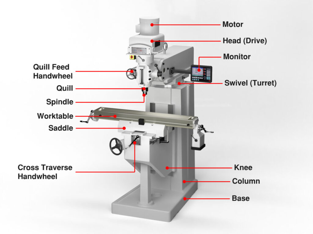
The primary components of a DIY CNC mill include a frame (often made from extrusions), linear rails, lead screws or ball screws, a spindle, servo or stepper motors, a controller, and the CNC software with a G-code interpreter.

The frame provides the structure and rigidity required for precise operations, ensuring the mill can handle the forces generated during milling. The spindle, attached to the frame, holds and spins the cutting tool. The stepper motor, such as the popular NEMA23, is controlled by the CNC software. It moves the spindle and the workpiece relative to each other along the XYZ axes, with the X-axis representing side-to-side movement, the Y-axis in and out, and the Z-axis up and down.

You can make the frame from various materials, including epoxy granite, aluminum, or steel. The choice of material depends on your budget and the precision and stability you require. Aluminum is a good choice; it is sturdy and relatively easy to work with.

The spindle is one of the machineā€™s most critical parts, and you should choose it carefully. Ensure it has the correct speed and power to cut through the material you plan to machine.

The stepper motors move the spindle around, and their quality and specifications significantly impact the precision and smoothness of the machineā€™s operation. Choosing suitable motors involves considering your machineā€™s size, the spindleā€™s weight, and the type of material you plan to cut.

The controller represents the ā€˜brainā€™ of the DIY CNC machine, receives instructions from your computer, and translates them into movement. It controls the stepper motors and the spindle. You can buy a pre-made controller or make your own.

Check out options for buying individual components or kits at websites like https://buildyourcnc.com/CNCPlans.aspx.

Construct the Machine

Once all the parts are ready, you can start constructing the machine. Begin by building the frame, ensuring it is square and level. Next, install the stepper motors and the spindle, aligning them correctly. Connect the motors to the controller and make sure everything moves as expected.

Test your machine

Testing involves sending a design to the controller and letting the machine cut it out. By observing the results, you can make any necessary adjustments to improve performance.

Building a DIY CNC milling machine is challenging. Still, with thorough planning and execution, it can be a satisfying project, providing you with a versatile tool for future DIY projects.

What are the options for a worktable?

The work surface is where you will clamp your workpiece. On many professional machines, the work table has T-slots milled into the surface, allowing you to use T-nuts and bolts to secure your materials or vices. Others use a square piece of 18 mm birch-plywood to fasten the materials with screws and replace them when needed, providing an affordable work surface. You could also use MDF with anchor nuts and bolts, but avoid screws and nails in MDF since it doesnā€™t grip them as well as a plywood board.

Helpful hint: You could use your newly completed CNC machine to flat mill the work surface and call it your first project!

How challenging is it to build a CNC mill?

Designing and building a DIY CNC milling machine is an ambitious project requiring careful planning, precise execution, and a solid understanding of mechanical and electronic principles. In other words, itā€™s not for everyone!


Check out this full video of a talented and experienced man building a CNC mill. Remember that some people make things look easy because they know what they are doing, and this young man is an excellent example of this. He has all the tooling, including a nifty portable magnetic drill press, and he is an experienced welder with all the safety equipment and a welding machine. Unless he worked on this project full time, he likely invested at least six months and several thousand dollars into this project.


For a lower-end option, watch ā€œHow to Build a Homemade CNC Milling Machine Based on the V-SLOT OpenBuilds Systemā€. Although not in English, this lengthy video is helpful for understanding the details involved. Keep in mind that this and similar Chinese models available at Amazon are not robust machine tools and are limited to cutting wood, PCB, and other lightweight materials.

Advantages and Disadvantages of a DIY CNC Milling Machine Project

What are the advantages of DIY-ing your machine?

Creating your own CNC milling machine offers many advantages, primarily in customization, cost-effectiveness, and educational value.

When you build your own CNC machine, you can tailor it to your specific needs. Whether your projects require a particular size or special modifications, you have complete control over the design. You can adapt the machineā€™s capabilities to your specific applications, thus ensuring that it perfectly fits your requirements, a luxury not readily available with off-the-shelf solutions.

As for cost-effectiveness, building a CNC machine from scratch can be more economical than buying a ready-made one, especially if youā€™re a hobbyist or running a small-scale operation. Assembling your machine lets you control the budget and prioritize where you want to invest most, whether in higher quality components or advanced software.

Finally, the educational value of building a CNC machine is immense. The process involves understanding the fundamental principles of CNC technology, mechanical engineering, and electrical systems. Itā€™s an opportunity to acquire new skills and deepen your knowledge in these areas, which can be highly valuable for hobbyists and professionals. A hands-on experience in building a CNC machine aids in troubleshooting and maintenance tasks as you become familiar with every machine component.

Building your CNC milling machine can offer a customized, affordable, and educational solution for machining needs. Itā€™s an endeavor well worth considering for anyone interested in CNC technology.

What are the downsides of DIY-ing your CNC machine?

While undertaking this project can seem exciting, it carries several disadvantages worth considering. The first piece of advice: donā€™t underestimate the complexity of assembling a CNC milling machine. These machines require intricate calibration and precise installation of components, which can prove challenging for individuals without advanced technical skills.

Second, the time commitment required for a DIY project of this magnitude is considerable. Assembly, testing, and tweaking can consume significant hours you could spend on other projects. Moreover, the process is often trial and error, leading to potential frustration and project abandonment.

Third, cost implications can outweigh the benefits. While the initial perception might be that DIY saves money, the truth can be quite the opposite. The costs of individual parts, tools, and potential replacements for errors can quickly add up, possibly exceeding the price of a pre-assembled machine.

Finally, donā€™t ignore safety. Improper assembly or use of a CNC machine can lead to severe injuries. Professional manufacturers adhere to stringent safety standards that may not be part of a DIY approach.

While the sense of accomplishment from building a CNC milling machine can be rewarding, the potential drawbacks make it crucial to carefully weigh the decision before embarking on a DIY CNC Milling Machine Project.

Comparing DIY CNC Mills and Desktop CNC Mills from CNC Masters

  • Cost: DIY CNC mills can often be more affordable because the price primarily includes components and raw materials. However, CNC Mastersā€™ desktop machines, though more expensive, come fully assembled and ready to use.
  • Ease of Setup: DIY CNC mills require specific technical knowledge for assembly and calibration. In contrast, desktop CNC mills are pre-calibrated and ready to use out of the box.
  • Support and Warranty: With DIY CNC mills, troubleshooting and maintenance are up to you. CNC Masters, for example, offers warranty and support for their desktop CNC machines.
  • Reliability and Precision: DIY CNC mills can vary in reliability and precision depending on the quality of the build and the deflection on the longer axis. Desktop CNC mills from CNC Masters are built with quality components and have rigorous testing to ensure accuracy and reliability.
  • Software Compatibility: Depending on the controller, DIY CNC mills can be compatible with various software. Desktop CNC mills from CNC Masters come with their proprietary software, which might limit compatibility with other programs.
  • Time Investment: Building a DIY CNC mill requires a significant time investment in addition to skills in electronics and mechanics. CNC Mastersā€™ desktop CNC mills save time since they come fully assembled.
  • Safety: Desktop CNC mills from CNC Masters have safety features like emergency stop buttons and shielded wiring. Safety in DIY CNC mills depends entirely on the builderā€™s precautions and design.

Remember, the choice between a DIY CNC mill and a pre-built one, like those from CNC Masters, greatly depends on your needs, budget, skills, and time availability. Professionally produced machines benefit from years of design refinement and the use of premium materials, ensuring their durability and longevity, which makes a powerful case for choosing a high-quality CNC mill over a DIY alternative.

At CNC Masters, we offer three of the best Desktop CNC Mills, and they are all available online. These CNC machines provide compact power at an affordable price. CNC Masters offers options in small CNC machines to fit your work and budget. We sell only high-quality, USA-built machine tools with ball screws, a warranty, and excellent service ā€“ all at a competitive price!

Please email us directly at sales@cncmasters.com, call us at 626-962-9300, or visit our contact page. We look forward to hearing from you!

About Peter Jacobs

Peter Jacobs is the Senior Director of Marketing at CNC Masters, a leading supplier of CNC mills, milling machines, and CNC lathes. He is actively involved in manufacturing processes and regularly contributes his insights for various blogs in CNC machining, 3D printing, rapid tooling, injection molding, metal casting, and manufacturing in general. You can connect with him on his LinkedIn.

Have Questions? Need a Quote?

Looking for more information about our CNC machines and services? Contact us today.

Contact

Slide 1

29. Create a Peck Drilling Program in Circular or Rectangular Patterns
Using the Circular or Rectangular Drilling Wizards, you can program the machine to drill an un-limited series of holes along the X and Y planes. Program it to drill straight through to your total depth, use a high-speed pecking cycle, or deep hole pecking cycle. You can program the cut-in depth and return point for a controlled peck drill application to maximize chip clearance.

Slide 1

20. Change up to 30 tools with compensation, and store your tool offsets for other programs
The MX supports…

Slide 1

21. Use the optional ATC rack up to 8 tools for milling, drilling, and rigid tapping applications
The CNC Masters Automatic Tool Changer Rack and Tools (US Patent 9,827,640B2) can be added to any CNC Masters Milling Machine built with the rigid tapping encoder option. The tutorial will guide you through the set-up procedure using the ATC tools.

Slide 1

22. Use the optional Rigid Tapping Wizard without the need for tapping head attachments
When you order your CNC Masters machine, have it built with the optional rigid tapping encoder. You can take any drill cycle program and replace the top line with a tapping code created by the wizard to tap your series of holes up to 1/2ā€ in diameter.

Slide 1

23. Use the optional Digital Probe to scan the profile and/or pockets of your fun/hobby type designs to write your tool path program and machine out a duplicate of your original design To ā€œsurfaceā€ scan an object, you can program the probe along the X or Y plane. The stylus will travel over the part starting on the left side front corner of the object and work its way to the end of the part on the right side. Depending on how the stylus moves, it will record linear and interpolated movements along the X, Y, and Z planes directly on the MX Editor.
To ā€œpocketā€ scan an object containing a closed pocket such as circles or squares, the scan will start from the top front, work its way inside of the pocket, and scan the entire perimeter of the pocket.
Under the Setup of the MX software you will find the Probe Tab which will allow you to calibrate and program your probe. Your ā€œProbe Stepā€, ā€œFeedā€, and ā€œData Filterā€ can also be changed on the fly while the probe is in the middle of scanning your object.

Slide 1

24. Use work offsets G54-G59 for nesting applications
The work offsets offer you a way to program up to six different machining locations. Itā€™s like having multiple 0.0 locations for different parts. This is very useful especially when using sub-routines/nesting applications.

Slide 1

25. Create a Rectangular Pocket / Slot with our selection of Wizards to help you build a tool path program
The Cycle Wizards for the mill or lathe makes it easy to create a simple tool path without needing to use a CAD and CAM software.
On this Wizard, the Rectangular Pocket / Slots, can be used to form a deep rectangular pocket into your material or machine a slot duplicating as many passes needed to its total depth.

Slide 1

26. Create a Circular Pocket Wizard
Input the total diameter, the step down, and total depth and the code will be generated.

Slide 1

27. Do Thread Milling using a single point cutter Wizard

Slide 1

28. Cut a gear out using the Cut Gear Wizard with the optional Fourth Axis

Slide 1

19. Disable the axis motors to manually hand crank each axis into place
Easily de-energize the axis motors by clicking [Disable Motors] to crank each axis by hand, and then press [Reset Control] to re-energize the axis motors.

Slide 1

30. The MX interface can easily be interchanged from Mill Mode to Lathe Mode
Use this interface for your CNC Masters Lathe. It contains all the same user-friendly features and functions that comes in Mill Mode. Simply go to the Setup page and change the interface.

Slide 1

31. Use Tool Change Compensation or the optional Auto Tool Changer Turret if your application requires more than one tool in a single program
You can offset the length and angle of each tool and record it under Tools in your Setup. The program will automatically pause the latheā€™s movement and spindle allowing you to change out your tool, or allowing the optional ATC Turret to quickly turn to its next tool and continue machining.
On the MX interface, you also have four Tool Position buttons. Select your desired T position, and the auto tool post will quickly turn and lock itself to that position.

Slide 1

32. Use the Lathe Wizard Threading Cycle to help you program your latheā€™s internal or external threads in inches or metric

Slide 1

33. Use the Lathe Wizard Turning / Boring Cycle to help you program simple turning and boring cycles without having to go through a CAM or writing a long program with multiple passes

Slide 1

34. Use the Lathe Wizard Peck Drilling Cycle to help you program your drill applications or for face grooving

Slide 1

35. Facing / Grooving / Part Off Cycle Wizards ā€“ with Constant Surface Speed
These cycles can be used with Constant Surface Speed allowing the spindle speed to increase automatically as the diameter of the part decreases giving your application a consistent workpiece finish. With CSS built into the wizard, there is no need to break down the cycle into multiple paths and multiple spindle speed changes.

Slide 1

36. This is our list of supported G and M codes which can be found under Tools > G Code/ M Code List in the MX
If you plan to use a third-party CAM software to generate your tool path program, use a generic FANUC post processor and edit it to match our list of codes. As an option, we also sell Visual mill/turn CAM software which comes with a guaranteed post processor for our machines to easily generate your tool path programs based on your CAD drawings.

Slide 1

37. Our pledge to you…

Slide 1

10. Run each tool path independently to study its movement
1. Run the machine on Trace mode. You can run each tool path independently, one line at a time to study the tool path movement on the machine to verify the position of the application and if any fixture/vise is in the way of the cutterā€™s path.

2. You can also verify your program by clicking on the Trace and Draw buttons together. This will allow you to view each tool path independently one line at a time in the Draw Window.

Slide 1

2. Clutter Free Interface
The MX is engineered for the CNC MASTERS machine so you do not have to fiddle with a detailed complicated configuration that can be overwhelming. Just load in the MX and start machining!2. Clutter Free Interface
The MX is engineered for the CNC MASTERS machine so you do not have to fiddle with a detailed complicated configuration that can be overwhelming. Just load in the MX and start machining!

Slide 1

3. Features Tour and Tutorials Included
The Features Tour will give you a quick run-down on all the features the MX can do for you. The Tutorials are easy to follow even for the first time CNC machinist.
Feel free to download the MX on any of your computers. We recommend downloading the MX along with your CAD and CAM software there at the comfort of your office computer to generate your tool path programs. You donā€™t need to be hooked up to the machine either to test your program in simulation mode.

Slide 1

4. Navigate and Edit Your Program through the MX interface with Ease
With a few clicks of the mouse or using touch screen technology, you can easily navigate through the MX interface importing saved programs into the Editor from the File drop down menu. Using standard windows features to edit your program you can then lock the Editor Screen to avoid accidental editing, and if you need to insert a line in the middle of a program, just click on [ReNum] to re-number your tool path list.
You can create a program or import CAM generated G-code tool paths into the Editor
The X Y and Z W arrow jog buttons are displayed from the point of view of the cutter to avoid confusion when the table and saddle are moving. You can also adjust your spindle speed and coolant control while jogging each axis.

Slide 1

5. Feed Hold ā€“ Pause in the Middle of your Program
Feed Hold lets you pause in the middle of a program. From there you can step through your program one line at time while opting to shut the spindle off and then resume your program.
You can also write PAUSE in the middle of your program and jog each axis independently while your program is in pause mode.

Slide 1

6. Hot Keys
Hot Keys is an alternative method to easily control your machine using your hard or touch screen keyboard. One can press P to pause a program, press S to turn Spindle On, G to run a program, Space Bar to Stop, J to record your individual movements one line at a time to create a program in teach mode.

Slide 1

7. Pick Menu ā€“ for conversational mode programming
Write FANUC style G-codes directly into the Editor or select commands off the [Pick] menu and write your tool path program in conversational mode such as what is written in the Editor box. You can even mix between conversation commands and G-codes in the same program.

Slide 1

8. Pick Menu List of Options
Use commands such as MOVE, SPINDLE ON/OFF, COOLANT ON/OFF, PAUSE, DELAY, GO HOMEā€¦. to write your tool path programs in conversational mode.

Slide 1

9. Draw the Tool Path to verify it before pressing Go
Hit Draw to view your tool path program drawing, check out its run time, or even simulate the tool path in 3D mode. This can be helpful to quickly verify your program before running it. You can also slow down or speed up the drawing or simulation process.
You can also hit Go within the Draw Window itself to verify the cutterā€™s position on the machine. The current tool path will be highlighted and simultaneously draw out the next path so you can verify what the cutter will be doing next on the program.

Slide 1

MX Software ā€“ Easy to Use, Easy to Learn ā€“ Included with your machine purchase
The MX software is designed to work seamlessly with your CNC Masters machine. It is made to work with Windows PC ā€“ desktop, laptop, or an all in one ā€“ on standard USB. Use it on Windows 8 or 10 64-bit operating systems.
No internal conversion printer/serial port to USB software or additional conversion hardware is used with the MX.

Slide 1

11. Counters display in Inches or Millimeters ā€“ Continuous Feed
1. When running a program, the counters will display a ā€œreal-timeā€ readout while the machine is in CNC operation without counting ahead of the movement.
2. The current tool path is highlighted while the machine is in operation without causing slight interruptions/pauses as the software feeds the tool path to the machine. The MX internally interprets a program ten lines ahead to allow for ā€œcontinuous machiningā€ avoiding slight interruptions as the machine waits for its next tool path command.
3. ā€œRun Timeā€ tells you how long it takes to run your tool path program.

Slide 1

12. Use the ā€œGo From Lineā€ command to start in the middle of your program
If you ever need to begin your program from somewhere in the middle of it, use [Go From Line] which you can find under Tools. The Help guide will walk you through how to position the cutter without losing its position on the machine.

Slide 1

13. Exact Motion Distance without over-stepping on an axis while jogging
Use ā€œRelative ONā€ to enter a specific coordinate to jog any of your axes to an exact location without having to write a program. Itā€™s like using ā€œpower feedā€ but easier. You can jog an exact distance on any of the axes without needing to keep the key pressed down and mistakenly over-step the movement releasing your finger too slowly off the jog button.
Letā€™s say you need to drill a hole exactly 0.525ā€ using the Z. So you enter 0.525 in the Z box. Next, adjust the JOG FEED RATE slider for the desired feed rate. Then ā€œclick onceā€ on the +Z or -Z button to activate the travel. In this case you click once the -Z button first to drill the hole exactly 0.525ā€. Then click once on the +Z button to drive the axis back up 0.525ā€.

Slide 1

14. Teach Mode ā€“ Jog Input
You can create a tool path program by storing each point-to-point movement by simply jogging an axis one at a time. Click on either of the Jog Input buttons to store each movement on the Editor Screen. You can then add Spindle ON, feed commands, and press GO to run the new program as needed. This is a great feature to help you learn to create a program by the movements you make on the machine without necessarily writing out an entire program first.

Slide 1

15. Override on the fly to adjust the Jog Feed to Rapid or the Spindle Speed during the middle of a program
1. Jog Feed and Rapid with Override: You can adjust feeds using the slider from slow minimum 0.1ā€³ per minute to a rapid of 100ā€³ per minute of travel. You can even micro-step your jog as low as 0.01ā€/min. The [-][+] buttons allow you to fine tune feeds in 5% increments while the program is in motion.
2. Spindle Speed with Override: You can adjust speeds using the slider from a slow minimum RPM to the max RPM according to the machine setup. The [-][+] buttons allow you to fine tune feeds in 5% increments while the program is in motion.

Slide 1

16. Adjust Counters using Pre-Set if you cannot begin the program from 0.00
In a situation where you cannot begin your cutter at itā€™s 0.00 location, you can ā€œPre-Setā€ directly into the counters by typing in your beginning coordinate. You can press Go from here to run your program. You can also ā€œzero allā€ or ā€œzeroā€ your counters independently. With one click of the [Return to 0.0] button, all axes will travel back to its respective 0.0 on the machine.

Slide 1

17. Set and Save your 0.00 position for future runs
Set and save your 0.00 position on the machine. These coordinates will be recorded as the first line of the program in the Editor Screen. Should you desire to return to this program at a later date, you only have to click on the Set Zero Return button. This will command the machine to automatically jog each axis to its saved ā€œsetā€ 0.00 position according to the recorded coordinates at the first line of the program.

Slide 1

18. Create a ā€œHomeā€ position to clear your application and run multiple times
Letā€™s say you need to machine one application times 100 pieces. This usually requires a jig to retain that physical 0.00 position. But in this case, you want the program to end with a clearance of the axes to easily switch out the next piece of stock and start again. With Save Home, you have the ability to save this offset (home) position while still retaining your Set Zero position where the machine will mill your part out. Pressing [Save Home] will record this new position under the Set Zero line in your program.
Pressing [Go Home] will jog your axes back to your ā€œsaved homeā€ position where you originally pressed the Save Home command. You can also input GO_HOME from the Pick Menu as its own tool path in your program. At the completion of your program the axes will end at your Home position. Replace your part, then press [Return to 0.0] button to allow the axes to return to its zero position, and press Go to start your next run.

previous arrow
next arrow