
Click the image to enlarge or to view as a slideshow.

The MX software is designed to work seamlessly with your CNC Masters machine. It is made to work with Windows PC – desktop, laptop, or an all in one – on standard USB. Use it on Windows 10 or 11 64-bit operating systems. No internal conversion printer/serial port to USB software or additional conversion hardware is used with the MX.

The MX is engineered for the CNC MASTERS machine so you do not have to fiddle with a detailed complicated configuration that can be overwhelming. Just load in the MX and start machining!
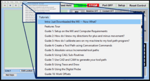 The Features Tour will give you a quick run-down on all the features the MX can do for you. The Tutorials are easy to follow even for the first time CNC machinist. Feel free to download the MX on any of your computers. We recommend downloading the MX along with your CAD and CAM software there at the comfort of your office computer to generate your tool path programs. You don’t need to be hooked up to the machine either to test your program in simulation mode.
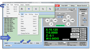 With a few clicks of the mouse or using touch screen technology, you can easily navigate through the MX interface importing saved programs into the Editor from the File drop down menu. Using standard windows features to edit your program you can then lock the Editor Screen to avoid accidental editing, and if you need to insert a line in the middle of a program, just click on [ReNum] to re-number your tool path list. You can create a program or import CAM generated G-code tool paths into the Editor. The X Y and Z W arrow jog buttons are displayed from the point of view of the cutter to avoid confusion when the table and saddle are moving. You can also adjust your spindle speed and coolant control while jogging each axis.
 Feed Hold lets you pause in the middle of a program. From there you can step through your program one line at time while opting to shut the spindle off and then resume your program. You can also write PAUSE in the middle of your program and jog each axis independently while your program is in pause mode.
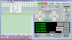 Hot Keys is an alternative method to easily control your machine using your hard or touch screen keyboard. One can press P to pause a program, press S to turn Spindle On, G to run a program, Space Bar to Stop, J to record your individual movements one line at a time to create a program in teach mode.
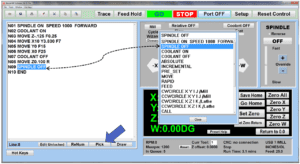 Write FANUC style G-codes directly into the Editor or select commands off the [Pick] menu and write your tool path program in conversational mode such as what is written in the Editor box. You can even mix between conversation commands and G-codes in the same program.
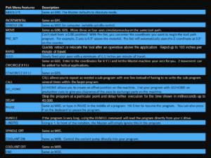 Use commands such as MOVE, SPINDLE ON/OFF, COOLANT ON/OFF, PAUSE, DELAY, GO HOME…. to write your tool path programs in conversational mode.
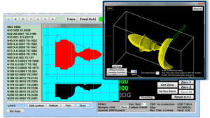 Hit Draw to view your tool path program drawing, check out its run time, or even simulate the tool path in 3D mode. This can be helpful to quickly verify your program before running it. You can also slow down or speed up the drawing or simulation process. You can also hit Go within the Draw Window itself to verify the cutter’s position on the machine. The current tool path will be highlighted and simultaneously draw out the next path so you can verify what the cutter will be doing next on the program.
 1. Run the machine on Trace mode. You can run each tool path independently, one line at a time to study the tool path movement on the machine to verify the position of the application and if any fixture/vise is in the way of the cutter’s path. 2. You can also verify your program by clicking on the Trace and Draw buttons together. This will allow you to view each tool path independently one line at a time in the Draw Window.
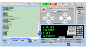 1. When running a program, the counters will display a “real-time” readout while the machine is in CNC operation without counting ahead of the movement. 2. The current tool path is highlighted while the machine is in operation without causing slight interruptions/pauses as the software feeds the tool path to the machine. The MX internally interprets a program ten lines ahead to allow for “continuous machining” avoiding slight interruptions as the machine waits for its next tool path command. 3. “Run Time” tells you how long it takes to run your tool path program.
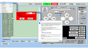 If you ever need to begin your program from somewhere in the middle of it, use [Go From Line] which you can find under Tools. The Help guide will walk you through how to position the cutter without losing its position on the machine.
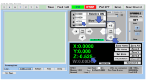 Use “Relative ON” to enter a specific coordinate to jog any of your axes to an exact location without having to write a program. It’s like using “power feed” but easier. You can jog an exact distance on any of the axes without needing to keep the key pressed down and mistakenly over-step the movement releasing your finger too slowly off the jog button. Let’s say you need to drill a hole exactly 0.525” using the Z. So you enter 0.525 in the Z box. Next, adjust the JOG FEED RATE slider for the desired feed rate. Then “click once” on the +Z or -Z button to activate the travel. In this case you click once the -Z button first to drill the hole exactly 0.525”. Then click once on the +Z button to drive the axis back up 0.525”.
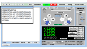 You can create a tool path program by storing each point-to-point movement by simply jogging an axis one at a time. Click on either of the Jog Input buttons to store each movement on the Editor Screen. You can then add Spindle ON, feed commands, and press GO to run the new program as needed. This is a great feature to help you learn to create a program by the movements you make on the machine without necessarily writing out an entire program first.
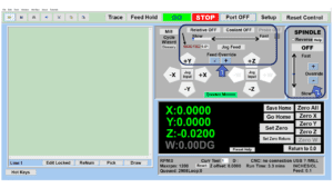 1. Jog Feed and Rapid with Override: You can adjust feeds using the slider from slow minimum 0.1″ per minute to a rapid of 100″ per minute of travel. You can even micro-step your jog as low as 0.01”/min. The [-][+] buttons allow you to fine tune feeds in 5% increments while the program is in motion. 2. Spindle Speed with Override: You can adjust speeds using the slider from a slow minimum RPM to the max RPM according to the machine setup. The [-][+] buttons allow you to fine tune feeds in 5% increments while the program is in motion.
 In a situation where you cannot begin your cutter at it’s 0.00 location, you can “Pre-Set” directly into the counters by typing in your beginning coordinate. You can press Go from here to run your program. You can also “zero all” or “zero” your counters independently. With one click of the [Return to 0.0] button, all axes will travel back to its respective 0.0 on the machine.
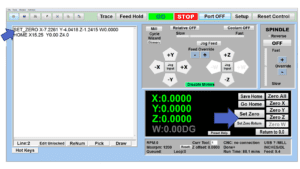 Set and save your 0.00 position on the machine. These coordinates will be recorded as the first line of the program in the Editor Screen. Should you desire to return to this program at a later date, you only have to click on the Set Zero Return button. This will command the machine to automatically jog each axis to its saved “set” 0.00 position according to the recorded coordinates at the first line of the program.
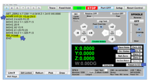 Let’s say you need to machine one application times 100 pieces. This usually requires a jig to retain that physical 0.00 position. But in this case, you want the program to end with a clearance of the axes to easily switch out the next piece of stock and start again. With Save Home, you have the ability to save this offset (home) position while still retaining your Set Zero position where the machine will mill your part out. Pressing [Save Home] will record this new position under the Set Zero line in your program. Pressing [Go Home] will jog your axes back to your “saved home” position where you originally pressed the Save Home command. You can also input GO_HOME from the Pick Menu as its own tool path in your program. At the completion of your program the axes will end at your Home position. Replace your part, then press [Return to 0.0] button to allow the axes to return to its zero position, and press Go to start your next run.
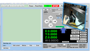 Easily de-energize the axis motors by clicking [Disable Motors] to crank each axis by hand, and then press [Reset Control] to re-energize the axis motors.
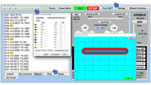 The MX supports… Tool Height Compensation allows for accurate height offsets when making a tool change using quick change tools within a program. Up to 30 tool changes can be made. This feature can be very effective for improved productivity if your application requires several tool changes. Store a library of tool offsets in the Setup > Tools window. You can choose any tool 1 – 30 by writing a T# command on its own line in a program. With a T command, the spindle will automatically shut off and retract up to exchange tools without needing to write extra lines of code. Tool Radius Offsets can also be done. If you choose to use a G41/G42 for a radius tool offset, you can enter the diameter in the Tools Window under Setup, and the machine will offset the radius of the tool. Diameter of Tool: By entering the size of the cutter in the Setup > Tools Window, you can also view the tool paths according to cutter size denoted by a different color in the Draw window.
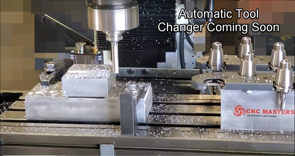
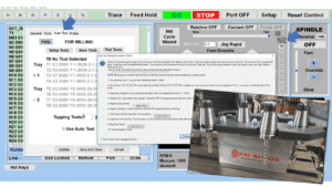 The CNC Masters Automatic Tool Changer Rack and Tools (US Patent 9,827,640B2) can be added to any CNC Masters Milling Machine built with the rigid tapping encoder option. The tutorial will guide you through the set-up procedure using the ATC tools.
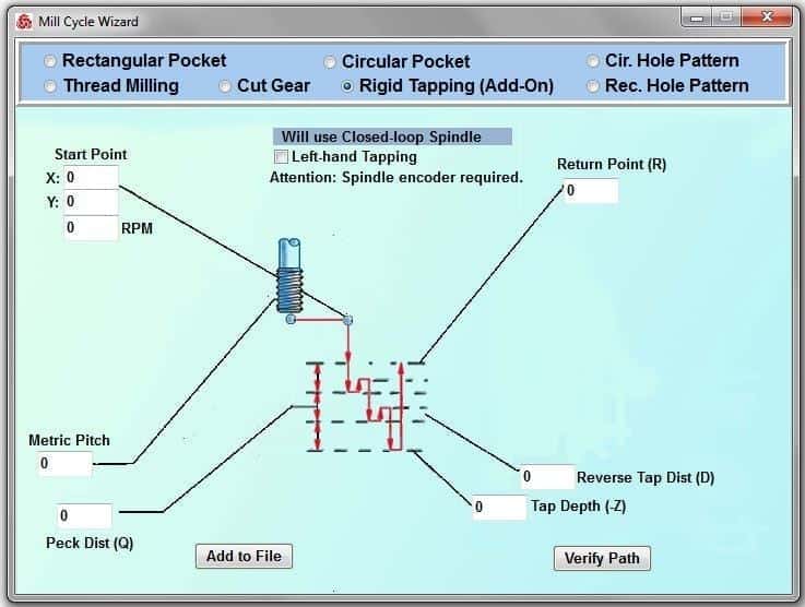
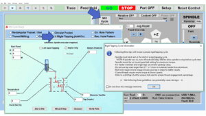 When you order your CNC Masters machine, have it built with the optional rigid tapping encoder. You can take any drill cycle program and replace the top line with a tapping code created by the wizard to tap your series of holes up to 1/2” in diameter.
 To “surface” scan an object, you can program the probe along the X or Y plane. The stylus will travel over the part starting on the left side front corner of the object and work its way to the end of the part on the right side. Depending on how the stylus moves, it will record linear and interpolated movements along the X, Y, and Z planes directly on the MX Editor. To “pocket” scan an object containing a closed pocket such as circles or squares, the scan will start from the top front, work its way inside of the pocket, and scan the entire perimeter of the pocket. Under the Setup of the MX software you will find the Probe Tab which will allow you to calibrate and program your probe. Your “Probe Step”, “Feed”, and “Data Filter” can also be changed on the fly while the probe is in the middle of scanning your object.
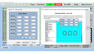 The work offsets offer you a way to program up to six different machining locations. It’s like having multiple 0.0 locations for different parts. This is very useful especially when using sub-routines/nesting applications.
 The Cycle Wizards for the mill or lathe makes it easy to create a simple tool path without needing to use a CAD and CAM software. On this Wizard, the Rectangular Pocket / Slots, can be used to form a deep rectangular pocket into your material or machine a slot duplicating as many passes needed to its total depth.
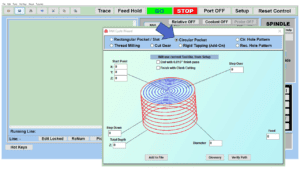 Input the total diameter, the step down, and total depth and the code will be generated.
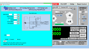
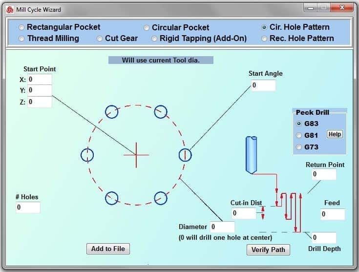
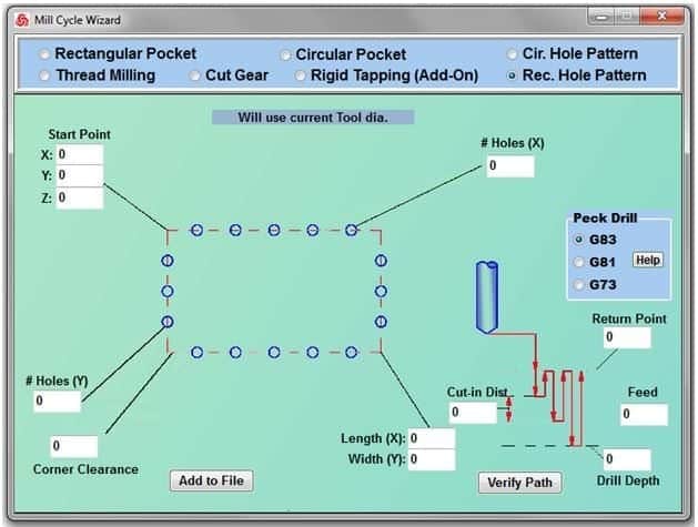
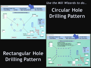 Using the Circular or Rectangular Drilling Wizards, you can program the machine to drill an un-limited series of holes along the X and Y planes. Program it to drill straight through to your total depth, use a high-speed pecking cycle, or deep hole pecking cycle. You can program the cut-in depth and return point for a controlled peck drill application to maximize chip clearance.
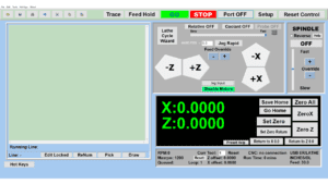 Use this interface for your CNC Masters Lathe. It contains all the same user-friendly features and functions that comes in Mill Mode. Simply go to the Setup page and change the interface.
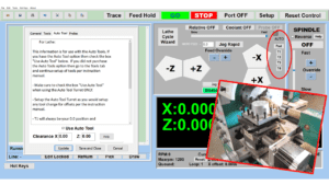 You can offset the length and angle of each tool and record it under Tools in your Setup. The program will automatically pause the lathe’s movement and spindle allowing you to change out your tool, or allowing the optional ATC Turret to quickly turn to its next tool and continue machining. On the MX interface, you also have four Tool Position buttons. Select your desired T position, and the auto tool post will quickly turn and lock itself to that position.
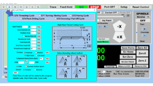
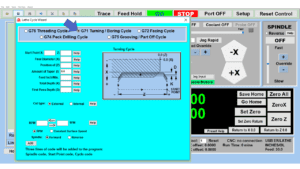
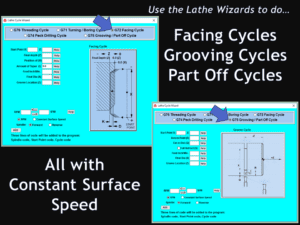 These cycles can be used with Constant Surface Speed allowing the spindle speed to increase automatically as the diameter of the part decreases giving your application a consistent workpiece finish. With CSS built into the wizard, there is no need to break down the cycle into multiple paths and multiple spindle speed changes.
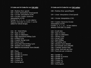 If you plan to use a third-party CAM software to generate your tool path program, use a generic FANUC post processor and edit it to match our list of codes. As an option, we also sell Visual mill/turn CAM software which comes with a guaranteed post processor for our machines to easily generate your tool path programs based on your CAD drawings.
Our custom CNC MASTER MX Software is included with every purchase of our CNC mills, lathes, and router machines. Run our CNC Software on Windows 10 or 11, Touch Screen Desktop, or Laptop PC by standard USB port connection.
Test out the new Master MX to run your CNC Mill. Give us a call at 626-962-9300 to request your free demo.
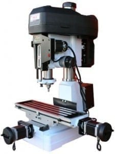
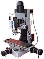
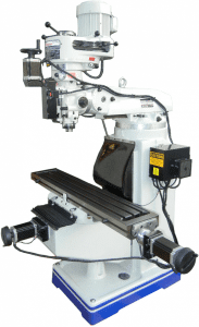
The MX CNC Software will run any of these milling machines. Compare for yourself:
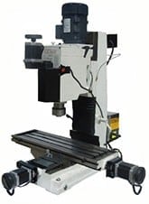
The CNC MASTERS MX Control Unit is controlled by the user friendly MASTER MX software via USB port, the standard in computer communication. All axis motors plug directly into the Control Unit and it is the Master MX that drives the axes to their correct coordinates.
The Master MX comes with wizards to easily generate a software-free file without using Computer Aided Manufacturing (CAM) software or 3D CAD software.
Easy Wizard Cycles for quick tool path creations such as circle pocketing, slots, rectangular pocketing, gear cutting, thread milling, rigid tapping (with optional encoder kit) and peck drilling applications.

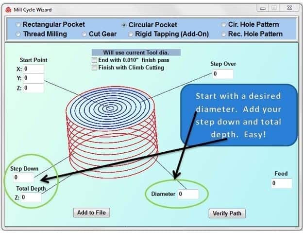
One of many Cycle Wizards. On this window, create a circular pocket without using CAD and CAM software.
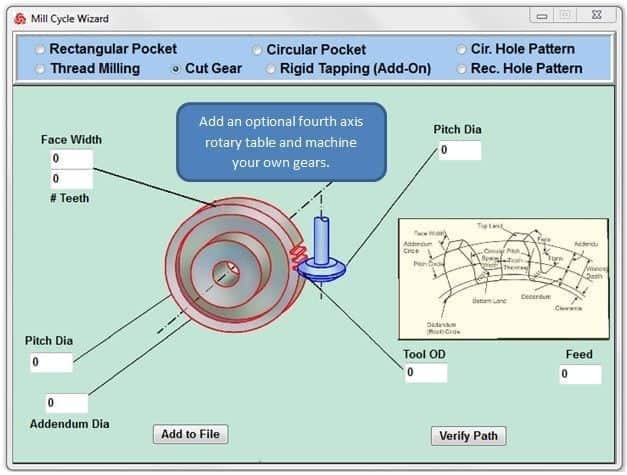
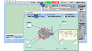
CNC machine your own gears and splines adding a cnc fourth axis.
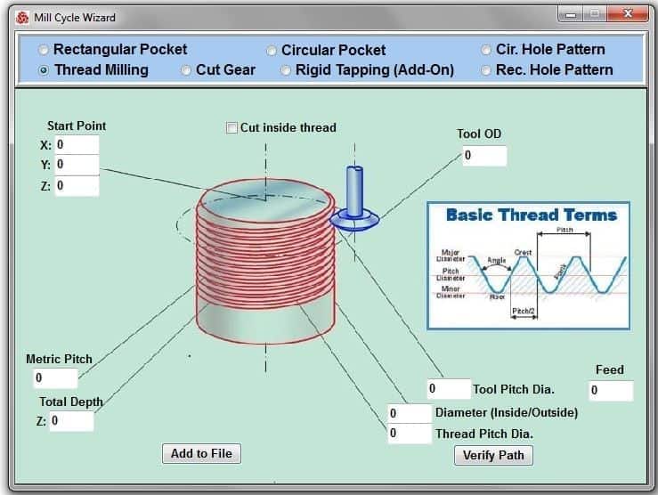
Easily create a helical movement driving X, Y and Z at the same time for thread milling.
Do all sorts of drilling cycles from high speed pecking to deep hole drilling operations.
The MX CNC software can also run standard FANUC G-code files from other CAD-CAM software such as MasterCAM, SmartCam, SurfCam, etc.
- Don’t know G-codes? Choose your Conversational Commands from our Pick Menu and simply type in your coordinates or mix it in with G-code commands right in the Editor.
ABSOLUTE
INCREMENTAL
SPINDLE ON
SPINDLE OFF
COOLANT ON
COOLANT OFF
MOVE
RAPID
FEED
CWCIRCLE
CCWCIRCLE
CALL
GO HOME
DELAY
PAUSE
FEED HOLD
/NOTES
END - View your tool path program in 2D or 3D in Simulation Mode.
- Use your touch screen monitor – desktop or laptop – Windows 10 or 11 – 64 bit operating systems to drive your CNC machine in pendant style.
- The MX is designed for PC use. Dedicate your PC or or order from us an All in One Touch Screen Computer with mounting arm for your machine.
- No additional hardware needed. Plugs in by simple USB connection. The CNC Masters MX Control Unit is built with direct USB connection. No internal port conversions or having to use other hard-to-locate platforms.
The MX CNC control software also features its own programming language. It uses plain conversational language like “Move, Absolute, Incremental, Repeat, Rapid, Feed, Spindle on, etc.,” which are all self explanatory. These commands are conveniently picked from the pull-down menus and placed on the main screen editor ready for the user to complete. For example, you need a number of steel pieces drilled with 100 holes, each of 1/2″ dia. by 1″ deep at 0.600 centers. With a simple program, the CNC Masters machine can do this operation with minimal supervision. The program will look like this:
- PROGRAM SAMPLE:
- N001 ABSOLUTE
- N002 MOVE X0 Y0 Z0
- N003 SPINDLE ON FORWARD SPEED 400 RPM
- N004 COOLANT ON
- N005 INCREMENTAL
- N006 CALL ROW 10 TIMES
- N007 SPINDLE OFF
- N008 COOLANT OFF
- N009 MOVE X0 Y0 Z0
- N010 END /MAIN PROGRAM
- N011 ROW /BEGIN SUBPROGRAM
- N011 MOVE Y-0.6
- N012 CALL DRILL_COLUMN 10 TIMES
- N013 END /ROW SUBPROGRAM
- N014 DRILL_COLUMN /BEGIN SUBPROGRAM
- N015 MOVE X.6
- N016 FEED 1.0 /INCHES PER MINUTE
- N017 MOVE Z-1.1
- N018 RAPID
- N019 MOVE Z1.1
- N020 END /DRILL CALL
The ability of the MASTER software to run and repeat “subprograms” with a single command line is a very powerful feature that will save the user considerable manual input and easily program custom “canned cycles” such as large DRILLING REPEATABLE FILES that can be written with just a few lines. Verifying a new program can be easily done with the “trace” facility. In this mode you can step a program one line at a time and check the XYZ position counters which serves as your DRO against the blueprint of the part, or you can activate the “Draw” window command to see a graphic simulation display in 2D or 3D of your file before you machine the part.
USE the CNC Jr., CNC Baron, CNC Max, or the CNC SUPRA with POPULAR CAD-CAM SOFTWARES
With the included G-CODES FILE INTERPRETER, the MX software can run files generated by many advanced CAM software packages, like VisualMill CAM which uses solids and surface machining technology. Or, use others like MASTERCAM, SURFCAM, RHINO, ARTCAM etc. All you need to do is setup your post-processor to match the CNC Masters Milling Machine, and you will be able to machine the most complex surface program that your machining requires. The maximum file size will be controlled by the storage space available on the hard drive of the host computer. With the MASTER editor you can create, edit, load, or mix G-codes with the MASTER command language.
The Master Software supports these standard Milling Machine G-Codes and M-codes:
- G00 = Position (Fast speed)
- G01 = Linear interpolation (Feed speed)
- G02 = Circular interpolation (CW)
- G03 = Circular Counter-clockwise interpolation (CCW)
- Format: X__Y__I__J__ I,J are relative distance from start to center. Incremental Z can be added for helical designs.
- G54 = Work Offset in Absolute Mode
- G55 = Work Offset
- G56 = Work Offset
- G57 = Work Offset
- G58 = Work Offset
- G59 = Work Offset
- G70 = Input in inches
- G71 = Input in millimeters
- G73 = High-Speed Peck Drilling Cycle
- G81 = Drilling Cycle
- G82 = Counter Boring Cycle
- G80 = Cancel Cycle
- G83 = Deep Hole Peck Drilling Cycle
- G90 = Absolute move (Modal)
- G91 = Relative/Incremental move (Modal)
- M00 = Pause
- M03 = Spindle on
- M04 = Spindle on reverse
- M05 = Spindle off
- M08 = Coolant on
- M09 = Coolant off
- M30 = End program
CNC Lathe G-Codes and M-codes:
- G00 = Position (Fast speed/Rapid)
- G01 = Linear interpolation (Feed speed)
- G02 = Circular interpolation (CW)
- G03 = Counter Clockwise Circular interpolation (CCW)
- Format: X__Z__I__K__ I,K are relative distance from start to center.
- G04 = Dwell time
- G20 = Input in inches
- G21 = Input in millimeters
- G71 = Turning Cycle
- G72 = Facing Cycle
- G74 = Peck Drilling
- G76 = Threading cycle
- G90 = Absolute move (Modal)
- G91 = Incremental move (Modal)
- M03 = Spindle on
- M04 = Spindle on reverse
- M05 = Spindle off
- M08 = Coolant on
- M09 = Coolant off
- M30 = End program
The MX supports…
- Tool Height Compensation up to Ten Tools within one program
- Tool Radius Offsets
- Feed Hold – step through each line in the program while opting to shut the spindle off and then resume program
- Pause in the middle of a program
- Coolant Control – optional
- Variable Spindle Control from 0 to max – optional
- Spindle Encoder for rigid tapping – optional
- Jog Feed/Teach Mode – create a program simply by jogging your axes
- Feed and Spindle Speed Over-Rides on the fly
- Relative exact movement positioning without writing a program — type in one movement and one-click your jog +/- arrow to drive that exact movement
- Start from another location other than 0.00 – just preset the new coordinates directly into the counters
- Press Go from another location in your program to drive your cutter
- Save 0.00 “and” a home offset position for future program runs
- Live Counter Display during computer numerical control movement without jumping ahead
- Displays and runs in either inches or millimeters
- 4th axis interpolation – simultaneous motion with the other axes – optional
- Rapids up to 150″/minute
- Trace Mode – Run one line independently at a time from beginning to end in your program to help you study the movement and establish your setup
- Editor Locked/Unlocked to easily write and edit your program and prevent accidental typing during a program run
- Displays Run Time
- Hot Keys – if your preference is to control your machine by keyboard such as the arrows, space bar, and letters simply open the Hot Keys command
- Run Sub-Routine programs using CALL for nesting applications or to mass produce the same part on a constant loop.
- Disable Motors — Easily disable motors to hand crank each axis. Re-engage the motors for cnc control in one click.
A testimonial from our customer, Holgate Enterprises in Florida using a CAD-CAM software on his CNC Supra Mill:
Hi CNC MASTERS,
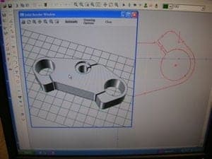
I wrote the program on BOBCAD. It was a little tricky but basically I used it for a training exercise kinda like mountain climbing! Bobcad uses what they call “Solids”. Under this category are “Primitives”. There are five choices of these primitives: Sphere, Cube, Cone, Cylinder and Torus.
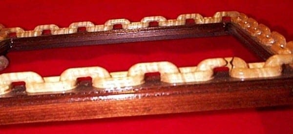
When using these, you must (always) instruct the program the size of these”parts”. A chain is made up basically of Torus’s and Cylinders. The torus being the ends (left and right) and the center portion is the cylinders. Unfortunately, the program will not write a half a torus. However, one can draw the whole torus and then”erase” half of it. After the first “Link” is successfully drawn and verified using the “render” command, then its just a matter of copying the link, pasting it (in the correct numerical distance to the right), rotating it 90 degrees (every other link is either vertical or horizontal.) and so on.
Upon completion, it has to be rotated every 90 degrees and ran again until the four quadrants are completed. Also, if you examine the picture, at the corners the two vertical sides finish with a half link turned 90 degrees and the top and bottom ones (shorter) must “meet” these corners too. So, as you can imagine, it was a real task and involved large degrees of visualization and so forth.

Back to CNC Baron Mill | Back to CNC SUPRA Mill | Back to CNC Max Mill | Back to CNC 1440 Lathe


