Whether you are directly involved in manufacturing or in a roundabout way, you have likely heard the term “CNC machining” used in various settings. Once an obscure label for a few high-tech machine tools, CNC systems have hit the mainstream, and CNC technology has been attached to nearly every machining operation.
Suppose you have ever wondered what CNC stands for. In that case, this article satisfies your curiosity. It gives you a better understanding of how advancements in machining technology are changing the landscape of manufacturing and other sectors of our economy.
Read on!
What is CNC Machining?
CNC (computer numerical control) machining is a manufacturing process utilizing a computer to guide the movements of various industrial machines. Although milling machines and lathes are the most recognizable CNC machines, that is only the tip of the iceberg today since practically any machine tool you can think of is now a candidate for a CNC control system.
Being an adaptable and cost-effective manufacturing process, CNC machining is compatible with a considerable array of materials and across various industries for numerous applications. Manufacturers use CNC machining for direct and indirect manufacturing processes or in combination with other techniques, making it an ideal method for rapid prototyping.
Although the advantages of using CNC machining appear in many industries, the healthcare sector stands out as an exceptional example of one that has seen the benefits of CNC up close as medically safe materials and advanced processes have come together to produce applications in the medical industry.
The close tolerances and complex shapes afforded by CNC machining mean that medical parts, including orthotics, implants, surgical instruments, and electronic enclosures, are more available for surgeons and other health care providers.
Remember that CNC machining operations work at removing material, known as a subtractive process. On the other hand, 3D printing is an additive or formative process that produces a physical part from a three-dimensional digital model by laying down thin layers of a material in succession.
How the CNC Machining Process Works
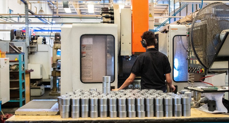
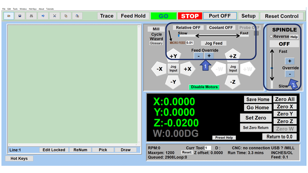
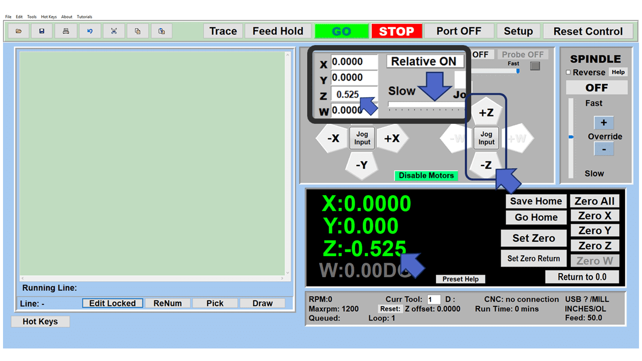
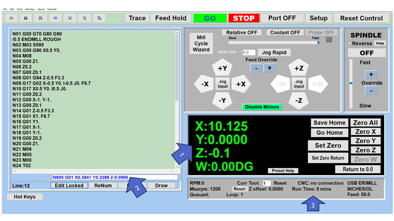
Unlike manual machines requiring a machinist or operator to manipulate controls for the machine’s movements, CNC machines in 2023 are fully automated, needing only digital files to provide the machine tool with instructions about cutting directions, feed rates, spindle speeds, and cutting tool selection.
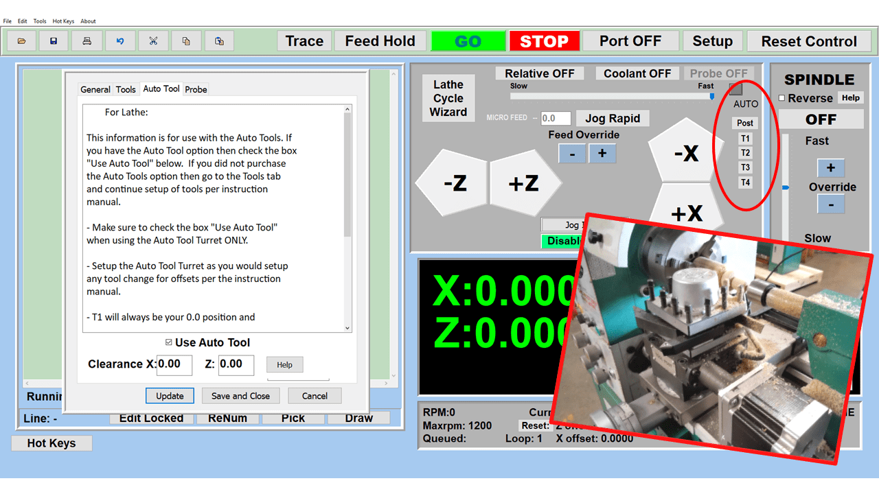
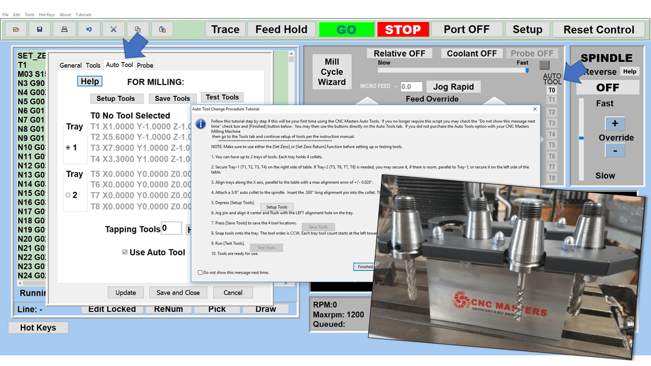
The machining processes might require several tools to produce a specific part, so machinists create a digital cutting-tool library, allowing the machine to change tooling based on the instructions in the program automatically.
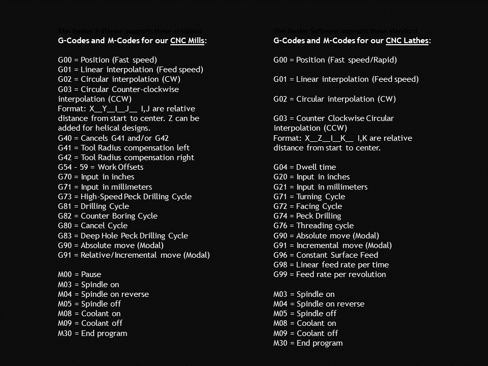
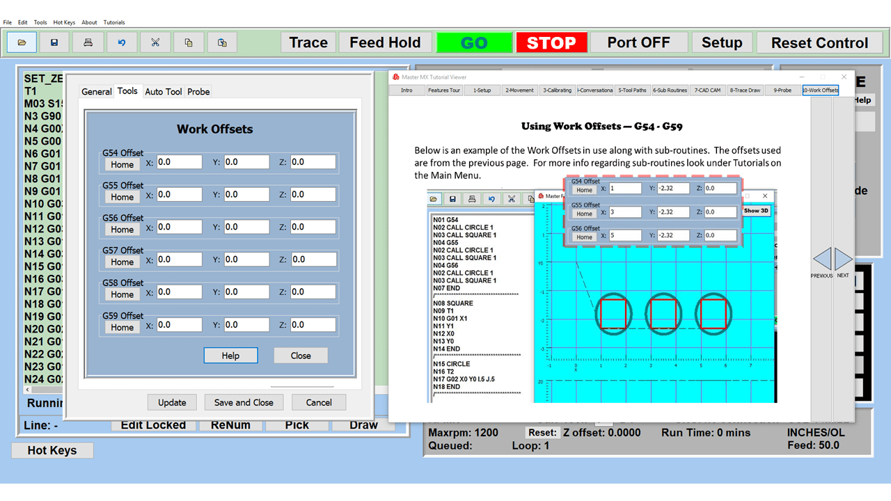
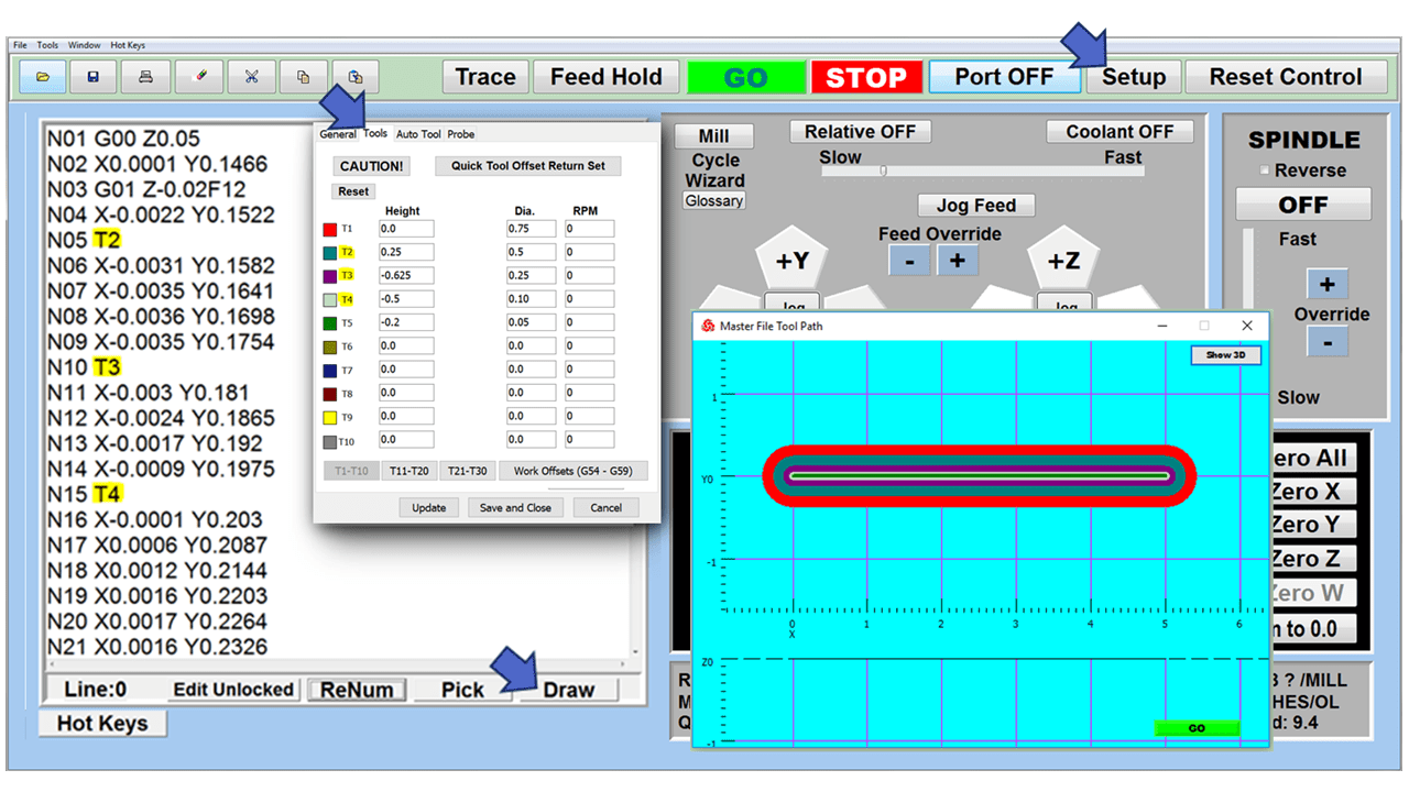
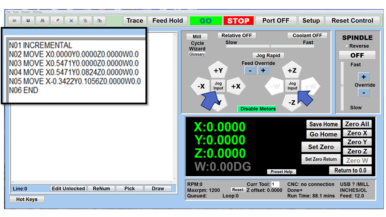
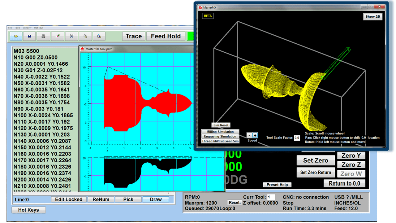
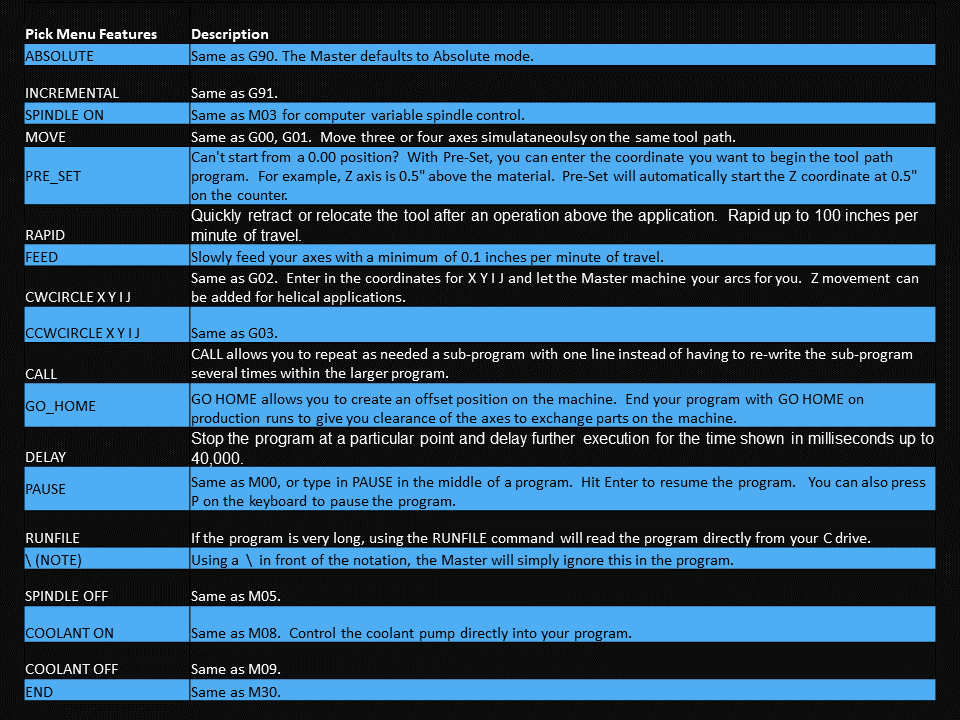
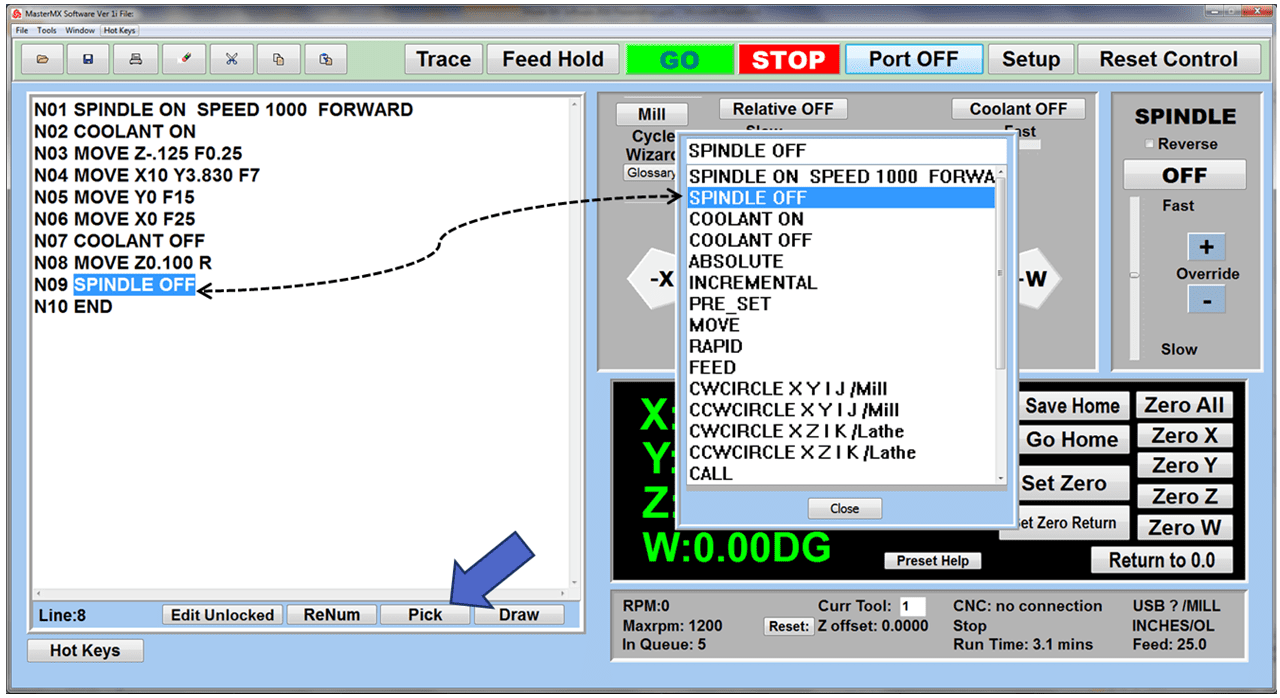
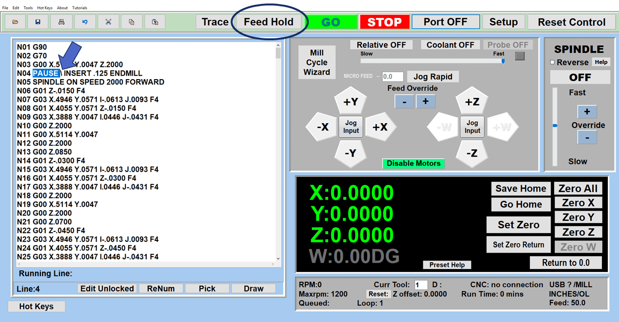
The CNC machining process begins with designing the parts in computer-aided design (CAD) software. The 3D model contains the necessary dimensions and properties of the final part, and the formatted CAD design file runs through a program, typically computer-aided manufacturing (CAM) software, to extract the part geometry and generate the digital programming code, typically in G-code and M-code.
The CNC program, a set of coordinates that guides the cutting head, is now ready to machine the part. Some programs come in CAD/CAM packages, so when CAD models are fed into CAM software from the same product family, no translation of files is required. Otherwise, the CAD files must be imported.
What Are The Advantages of CNC Machining?
Although CNC machining is most often a metal machining operation, it can provide many of the same advantages in woodworking. Using the best CNC machine for your applications will result in a host of benefits for your business. Here are a few of them:
- Less dependence on human labor and fewer mistakes: A skilled programmer and CNC machinist for setting up the machine might be required to get started. After that, software programs and G-codes control the machining process without human intervention or errors. This advantage looms large with today’s issues of worker shortages.
- A high degree of precision: A significant benefit of CNC machining is precision, especially when compared with manual machines. Creating parts that meet precise specifications and close tolerances is possible without constant attention from a skilled machinist.
- Repeatability: Nothing changes throughout the production process, regardless of the number of cycles, resulting in a consistent product.
- High-speed machining: CNC machines operate at the fastest speeds and feed rates, resulting in lower cycle times, less wasted material, and increased efficiency.
- Producing complex parts: The CNC machining process can create practically any designed part without adjusting the workpiece or depending on secondary operations.
- Scalability: CNC machines are ideal for production runs, but they are also scalable. You can program them to produce a single item or thousands, enabling manufacturers to use their resources and finances more efficiently.
- Improved safety: Operators interact with a CNC machine when entering a code or performing maintenance work. Other than that, the process is entirely automated, meaning machinists are not involved in a hands-on technique that requires them to be close to the cutting tool as with a manual machine.
- Lower costs: It might sound strange to see lower costs associated with CNC machines. After all, the initial price of a CNC machine is higher than that of a traditional manual machine. However, the lower operational costs more than compensate for the difference in price with fewer costly mistakes, higher output rates, and lower day-to-day production costs.
- Less operator training: Manual milling machines and lathes require highly-skilled machinists with years of schooling and hands-on training. Although some operator training for CNC machine tools will be needed, it won’t be nearly as detailed or time-consuming as a manual machinist’s education.
What is a CNC Machine? (8 Different Types)
1. CNC Milling Machines
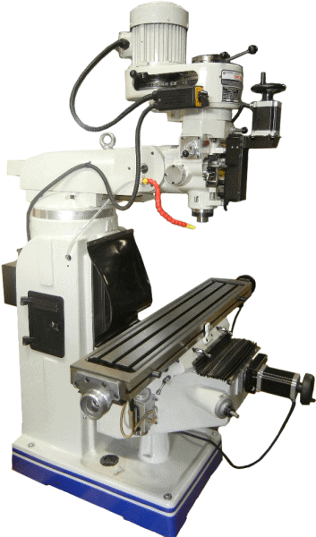
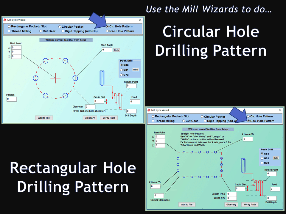
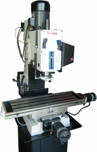
CNC mills are popular CNC machines, mainly for their versatility. They can cut slots, mill flat faces, machine complex shapes, bore precise holes, drill, tap, and perform numerous other operations. In its most basic form, the CNC milling machine can move along three axes: X-axis (left to right), Y-axis (front to back), and Z-axis (up and down), while other models have up to six axes, allowing for machining the most complicated parts.
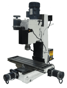
Most CNC milling machines are large and expensive, but there are exceptions. Smaller vertical Bridgeport-type milling machines, reasonably-priced and easier to learn and operate, bring the benefits of CNC machining to small businesses and even hobbyists. Also, a relatively new breed of CNC mills, aptly called “desktop milling machines” and selling for under $9,000, can fit on a workbench or in the corner of the garage, performing many of the same functions as the bigger, more expensive machines.
2. CNC Lathes
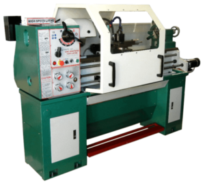
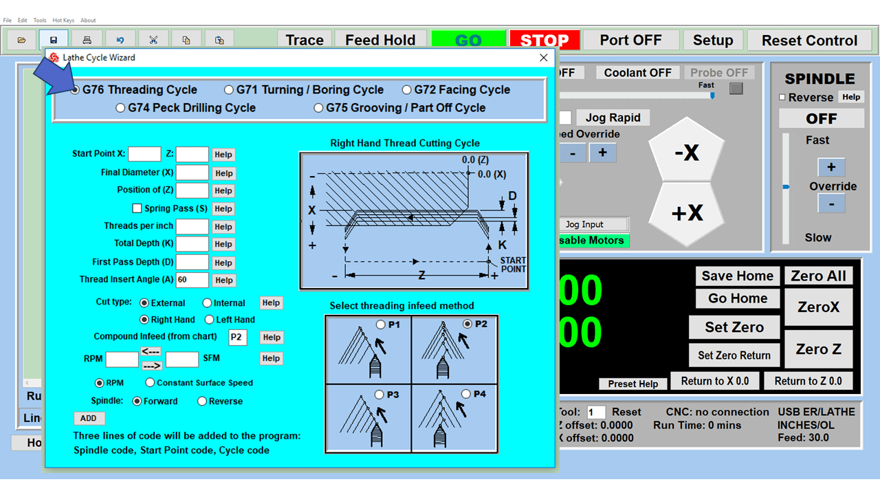
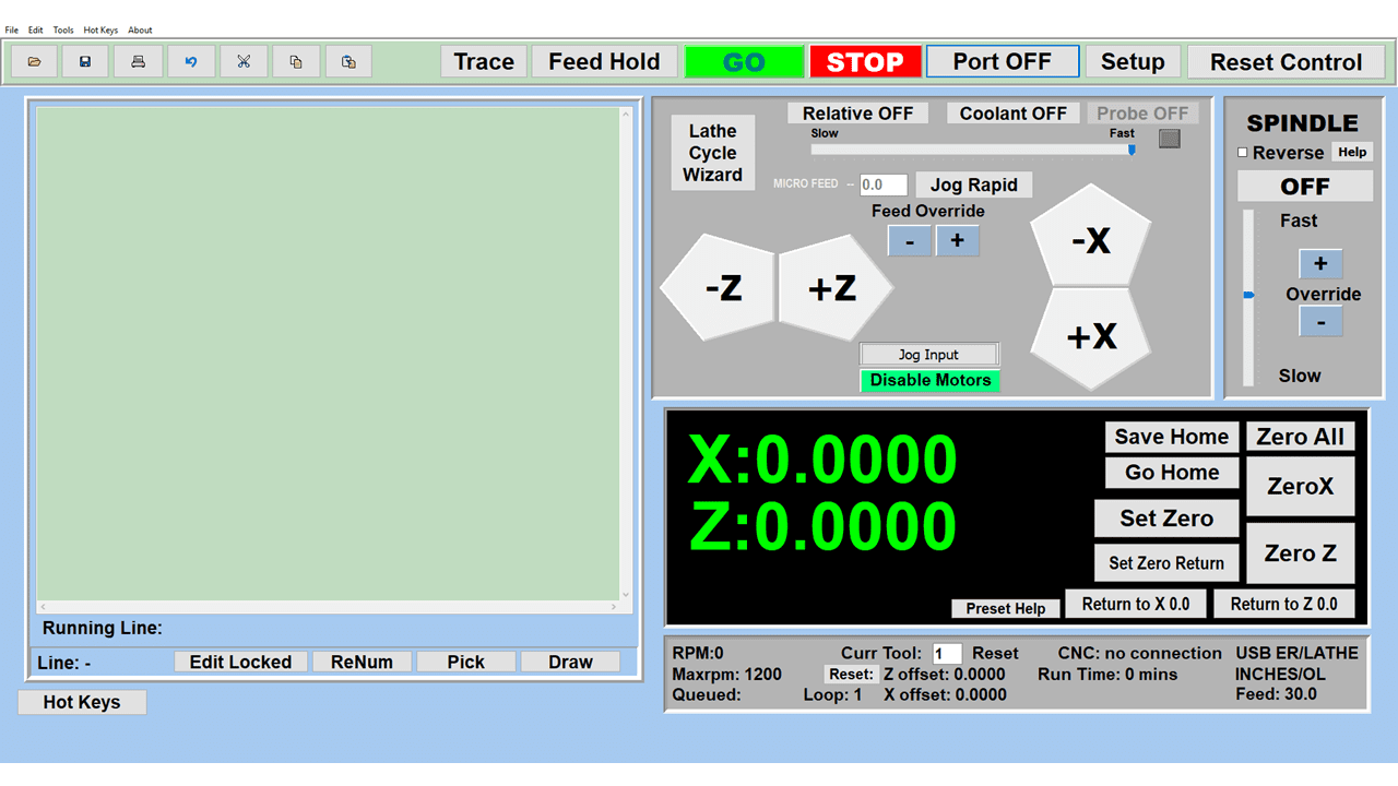
CNC lathes spin the workpiece as a cutting tool moves across its surface, creating cylindrical and conical shapes. Typically, CNC lathes have two axes: The X-axis moves perpendicular to the lathe chuck, determining the depth of cut and the diameter of the workpiece, while the Z-axis moves along the length of the workpiece, removing material. Systems with more axes are available, including:
- Y-axis—Perpendicular to X and Z (Up and down movement)
- A-axis—Rotation around the X-axis
- B-axis—Rotation around the Y-axis
- C-axis—Rotation around the Z-axis
CNC lathes can be programmed for several operations, including machining inside and outside diameters, threading, and boring. And similar to CNC mills, lathes can read G code and proprietary programming languages.
3. CNC Routers
CNC routers have much in common with milling machines but are primarily for woodworking and cutting softer materials like wood, foam, and plastic. Because of these material restrictions, routers run much faster than mills but without the accuracy of milling machines. The primary functions of CNC routers are to cut, engrave, and carve objects out of wood as a more accurate and high-speed substitute for hand-held routers, using router bits instead of end mills and milling cutters to do the job.
4. CNC Plasma Cutters
A plasma cutter work by sending an electric arc through a gas as it passes through a tiny opening. Plasma cutters raise the temperature of the gas with extreme heat, converting it to a fourth state of matter called plasma.
Using a portable plasma torch, it’s possible to cut through steel, aluminum, brass, and copper with little resistance, allowing for clean lines and sturdy construction. However, CNC plasma cutters for large-scale jobs have more features, although they are not portable, requiring a larger power supply. CNC plasma cutters are better when bigger workpieces, complex shapes, or thicker materials are involved.
5. CNC Waterjet Cutting Machine
A CNC water jet uses a high-pressure water stream to slice through various materials. For softer materials, like wood or rubber, the water alone is enough to cut it. Still, mixed with an abrasive substance like garnet or aluminum oxide, it can cut through more challenging materials.
The cutting process typically takes place underwater, with water pressures of 20,000 to 60,000 pounds per square inch (PSI). In other words, a waterjet has up to thirty times more pressure than a power washer, forced through a 0.010” to 0.015” diameter nozzle.
CNC waterjet machines complex shapes in hard metals like stainless and hardened steel resulting in high-precision components, and is an excellent industrial tool for gear cutting, slitting, drilling, profile milling, broaching, and sawing in industries such as mining, automotive, and aerospace.
6. CNC Grinders
A CNC grinder can come in a few different types, with cylindrical, roll, and surface grinders being the most common. All grinders use abrasive wheels to provide a smooth and high-precision finish operation to machined parts from a lathe or milling machine. Hardening of other heat treatments is often performed immediately before grinding.
Various abrasives are available for grinding, including diamond wheels, aluminum oxide, plated or vitrified CBN, and ceramic blend grinding wheels.
7. CNC Electrical Discharge Machines (EDM)
Sometimes referred to as “spark machining,” EDM is a form of precision machining that removes material using thermal energy instead of mechanical force. Electrical sparks of up to 12,000º C. remove material from a workpiece without subjecting it to excessive stresses. Shops turn to EDM when machining processes like CNC milling and turning cannot perform cuts such as sharp internal corners or extremely deep cavities.
There are two distinct types of EDM, die sink and wire, used in specific situations:
Die-sinking involves lowering a reverse-shaped graphite or copper electrode into a workpiece submerged in a dielectric fluid like oil. While submerged, a voltage is induced between the die and the electrically conductive workpiece.
Wire EDM cuts a shape in the workpiece using the exact mechanism of die-sinking, but a very thin wire replaces the electrode. Both methods work well with the most rigid materials.
8. CNC Laser Cutting Machines
CNC laser cutters focus a high-powered laser beam to engrave parts or cut them into custom shapes. The CNC machine has a laser head with a focusing lens and nozzle. The assembly focuses a column of high-intensity light on the workpiece to melt and cut it into various intricate shapes.
CNC laser cutting is a non-contact, thermal-based process to form the desired shape. CNC lasers use compressed gas to cool the focusing lens and expel the vaporized metal from the workpiece.
Common CNC Operations
CNC machine tools make it possible to perform numerous manufacturing operations, but here are the most common ones you will see in the manufacturing world today:
CNC milling will lead any list of machining operations since mills are the most versatile of the CNC machines and are capable of the following:
- Chamfer milling
- Profile milling
- Pocket milling
- Face milling
- Grooves and slots
- Drilling, tapping, and reaming
CNC lathe operations include:
- Turning
- Facing
- Boring
- Drilling, tapping, and reaming
- Knurling
- Chamfering
- Parting off
- Grooving
- Threading
Other CNC operations include:
- Precision grinding on flat parts
- Precision grinding on cylindrical workpieces
- EDM operations creating mold cavities
- Engraving
- Prototyping
- Non-contact cutting to intricate shapes
This list is incomplete since too many operations are possible with CNC machine tools, and the list grows yearly.
CNC Materials
Practically any machinable material—metal, wood, or plastic—is a candidate for CNC manufacturing, but choosing the best-suited material for the project counts more than anything else. Here are the top five materials typically selected for CNC machining and why they have become popular:
- Stainless steel alloys resist wear, distortion, and corrosion but are machinable in all grades, making them popular in many CNC machining projects.
- Aluminum alloys have an excellent strength-to-weight ratio, high thermal and electrical conductivity, quick machining, and natural corrosion resistance. Aluminum 7075, the most robust commercially-available aluminum alloy, is used in aerospace frames and high-performance recreational equipment.
- Carbon steel 1045 is a mild and less-expensive grade of carbon steel that is easy to machine, weldable, and hardened or heat-treated for hardness or rust and corrosion prevention.
- Although titanium is more expensive and not as machinable as other metals, it’s often chosen for CNC projects because of its high strength, toughness, and corrosion resistance. These attributes are essential in aerospace, military, and industrial applications.
- Nylon is an all-purpose thermoplastic used as an alternative to metal in CNC-machined parts. It is strong, impact-resistant, and chemical-resistant, making it ideal for electrical molding, fuel system components, food packaging, and gears.
How Companies Use CNC Machining Today
The Medical Field
Medical businesses count on CNC machining to produce high volumes of precision parts to meet their patients’ needs and keep essential components in their inventory. They also need various types of CNC machines with the ability to create customized pieces quickly. Because of the many medical devices available, CNC machining fits well with the medical industry, where CNC parts must be made in FDA-approved environments.
Here are a handful of the medical parts manufactured on CNC equipment:
- Orthotic devices
- Implants
- Medical instruments
- MRI machine components
- Research equipment
- Customized sterile packaging
During the designing stage, the CNC software lets engineers see the part as a three-dimensional object before machining begins. This pre-machining process ensures that the component has the correct dimensions so all the parts fit together as intended.
Oil and Gas Industry
The petrochemical industry cannot work with poorly machined parts and the issues that stem from them. They require precise components produced from CNC machines to prevent piston failures, cylinder breakdowns, or leaking valves.
Because they operate in remote areas, drilling rigs must also have close-tolerance, reliable parts since getting replacements could shut down production for days. All rig parts must work every time and for a long time, and only CNC machining can produce parts consistently without the occasional unpleasant surprise.
Some of the essential parts manufactured on CNC machines and used in the oil and gas industry include:
- Pistons
- Cylinders
- Rods
- Pins
- Valves
Aerospace Industry
One of the trademarks of the aerospace industry is its requirement for complex, customized, and accurate components. Aerospace CNC machining must meet incredibly tight tolerances, and CNC machinists must meet these standards while working with some of the most challenging materials, such as titanium and nickel.
The aerospace industry needs various parts for the aircraft and aircraft service equipment, including:
- Landing gear components
- Airfoils
- Manifolds
- Various bushings
- Electrical connectors
By employing CNC machining to produce components, the aerospace industry receives the customized parts and the close tolerances required.
Becoming a CNC Machinist
A CNC machinist is a programmer, set-up person, and skilled operator of CNC machinery. It’s a critical position within the modern machine shop, requiring blueprint reading, computer, math, and analytical skills. This person might need to be proficient in working with 5-axis CNC machine tools or managing a group of CNC machines, also known as a “cell,” in a two-person job shop or large corporation.
Although there are multiple paths to becoming a CNC machinist, they all start with a high school diploma or GED. Becoming a certified CNC machinist doesn’t always require a degree, but having accredited skills and training hours typically does. Corporations often prefer an associate degree, and having one usually pays better.
Here are a few paths to consider:
Technical and Community Colleges
These schools often work with a local high school to offer courses on basic manufacturing and then set up an internship with a local manufacturer. Companies prefer to recruit from these local vocational and technical schools since the skills they teach are in demand, and they have established a long and trusting relationship.
High School Programs
In many states, high school students can earn a machining certificate while still in school. This course could earn them credits toward completing an associate degree from a local technical and vocational school or community college. An associate degree program takes two years, and some states even allow you to earn a two-year associate degree during your last two high school years.
CNC Machinist Apprenticeship Programs
Sometimes called “earn and learn” programs, registered apprenticeships pair local businesses with paid students working toward journeyman machinist status. The typical requirements for a two-to-four-year machinist apprenticeship program registered with the U.S. Department of Labor include the following:
- 2,000 hours of on-the-job learning per year with apprenticeship standards established by the employer
- 144 hours of education or related training instruction (RTI) per year
Apprenticeships are an excellent avenue for learning through occupational-specific curricula and on-the-job performance standards that teach job skills in your workplace.
No matter which route you take toward a career as a CNC machinist, you will likely find it rewarding, challenging, and lucrative!

