You’ve got a new mini milling machine. You’ve got the raw material. And you’ve even watched a few YouTube videos to get a bit more familiar with your new mill.
If you’re really an over-achiever, you might even have read part of the user’s manual. But you still might be running up against a dead-end; what should you make first?
There are literally dozens of beginner mill projects and an equally large number that can be done on either a metal lathe or a mini mill. Most are decorative – various knick-knacks and technical pieces designed to give you practice performing certain operations on your mill. There’s nothing wrong with pieces that are more fancy than functional, but most of those projects will go straight to the shelf and sit there, collecting dust.
On the other hand, spending some of your first days with your new machine creating simple tools will expand your technical abilities as well as your toolkit. And more likely than not, you’ll return to those tools time and time again throughout the years, proof of your DIY success.
So for the sake of this list, we’ve assembled ten tool-based projects, and then five more decorative ones. The decorative projects that did make the list are a bit more challenging and, in some cases, at least moderately useful.
These projects can generally be done on either a manual or CNC milling machine, although some – like the chess set further down – will be easiest on a CNC mill.
So break out your little machine and load up on supplies. It’s time to get working!
Beginning DIY Mill Projects to Grow Your Toolbox
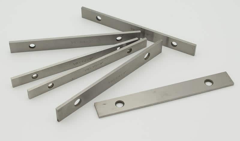
Soft Parallels
The workpiece mounts to the bed of your benchtop mill; so what happens if you need to drill through it? Without something to create some space between the two, you’ll either drill a hole in the bed of your mill or ruin your bit (and perhaps both.)
Soft parallels are the simple solution. The key is to cut pieces that are perfectly parallel and symmetrical – at that point, you can create as many through-holes as you want. And if you make them out of aluminum (the “soft” part) then you can be sure you won’t ruin your bit if you drill through them accidentally.
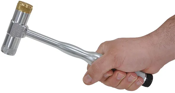
Machinist‘s Hammer
Simple, straightforward – and nearly indispensable. Used to power a hole punch through sheet metal, knock two parts together, and just about anything else you could imagine. Machinist’s hammers aren’t complicated to make, but in one tool you’ll deal with a number of simple but different geometries.
Round hammer heads, the cylinders of the handle and width of the head, any chamfer or contouring on the handle – this project will teach you the basics without putting too much on your plate to begin with. And in the end, you’ll have a perfectly serviceable addition to your toolbox, even if it isn’t perfect.
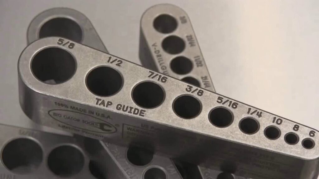
Tap Guide
Conceptually, this is one of the simpler projects on the list. But creating an accurate tap guide will force you to be precise, keeping all your measurements in order. The end result will be a go-to tool for sizing any holes and threading.
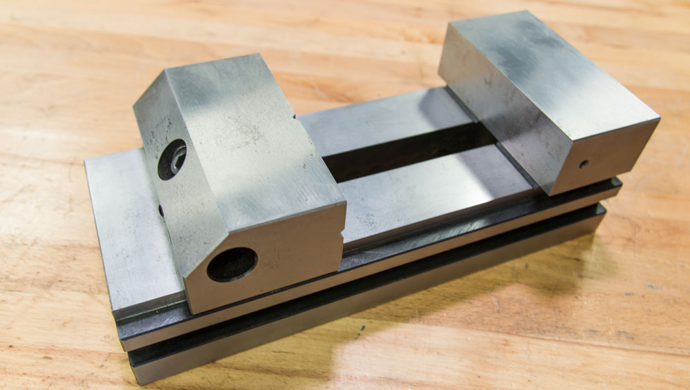
Toolmaker’s Vise
A good vise is a next step past the tap guide. Same basic blocky shape, but with a few simple moving parts. Machinists can never have too many blocks and vises – there are simply too many parts to hold in place all around the shop. You can make a toolmaker’s vise as large or small as you think you’ll need, making them a great choice for a mini milling machine operator.
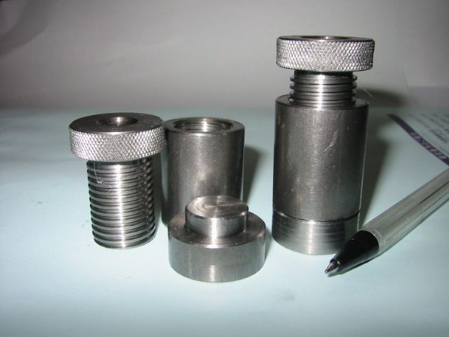
Screw Jacks
When soft parallels aren’t enough and you need a bit more clearance, screw jacks can be just the ticket. Easy-to-make and adjustable, they provide extra clearance and support for oddly-shaped workpieces.
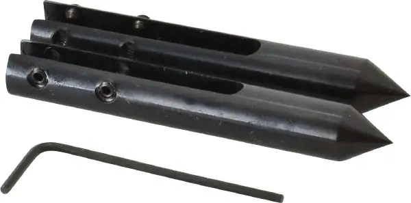
Calliper Center Distance Attachments
Another project that’s beyond simple in theory, but does require a lot of precision. They are two simple slide-on attachments for your indispensable set of calipers. They let the machinist measure the width of through-holes, bolts, and just about anything else you’ll need. This project will give you experience using a collet on a lathe, which is something every beginner needs!
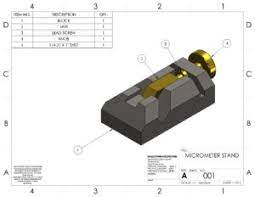
Micrometer stand
The world of machine tools requires precision, and a good micrometer is a machinist’s best friend. Crafting your own micrometer stand removes the “shakiness” factor, allowing you to take steady and reliable readings. The stand itself isn’t difficult to make, which means it’s a great chance to practice your finishes to craft a piece that stands out.
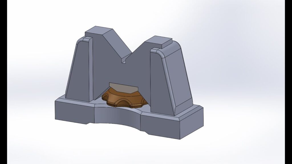
Vee Blocks
Vee blocks consist of two parts – the block with the v-shaped wedge, and the actual vise that rests on top. Together, the two form a vee block that’s used to clamp irregular and cylindrical shapes and hold them securely. These can be made in two stages depending on the maker’s skill – first, the vise, which is simpler, and then the base, which is slightly more difficult.

123 SuperBlocks
It’s easy to imagine these as the brainchild of a frustrated but brilliant machinist. Each block is filled with counterbored threaded holes in an alternating pattern. The resulting blocks can be securely fastened in a dizzying array of configurations, even twisted and stacked on top of each other. They make the perfect clamping system for any mill or mini lathe. You can also use them as supports when you need extra clearance, or to level out asymmetrical workpieces.
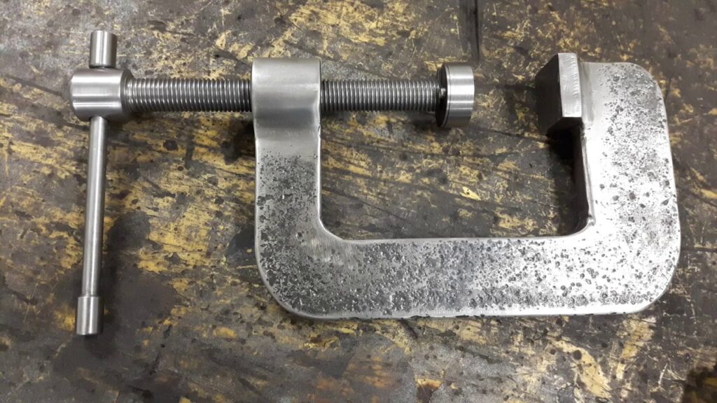
C-clamps
Workshop standbys the world over, C-clamps let you secure just about any two objects together. The design is simple – the body of the clamp is a single curved piece of metal, fitted with an adjustable screw and fastener. C-clamps are another opportunity for budding machinists to practice making accurate cuts as well as perfecting their finishes.
Technically Challenging and Aesthetically Pleasing: Projects to Practice Your Techniques
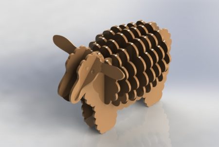
CNC Sheep
Ok, it doesn’t sound exciting – but the CNC sheep has been more than one machinist’s first project. The technical challenge comes in cutting out a series of shapes to exact dimensions, and then fitting them together.
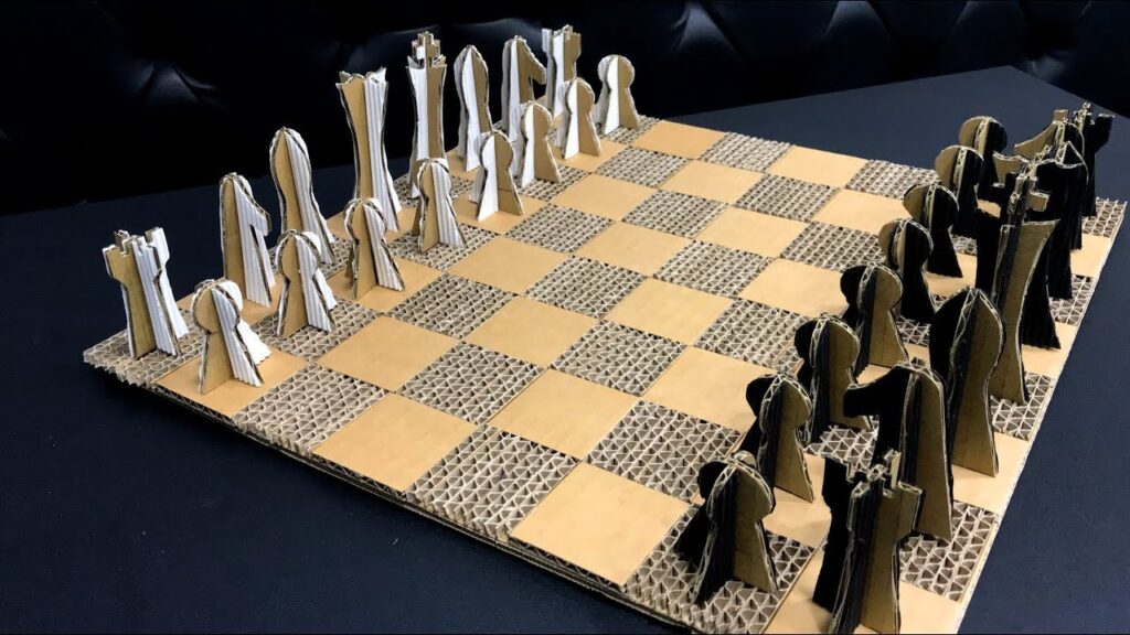
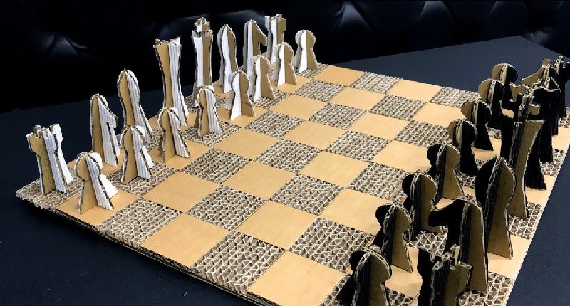
Chess Set (or Chesspiece)
Feeling confident? Tackle an entire chess set! Or if you’re a bit more reasonable, work on one piece at a time. The design is up to you, making this a project to challenge you on both planning and execution.
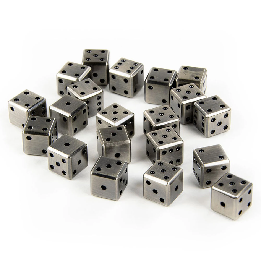
Metal Dice
Simple but striking. Cutting perfectly precise cubes is a great starting point, and drilling the dots and finishing the dice will challenge your artistic side.
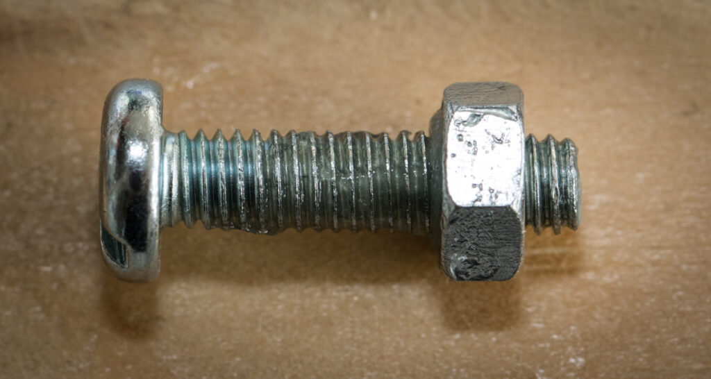
Bolt and Captive Nut
More of a conversation piece than anything else, the nut-and-bolt project is a great way to learn the intricacies of threading.

Turner’s Cube
A cube inside a cube inside a cube – the Turner’s Cube is as fascinating as it is deceptively simple. By using smaller bits and machining carefully, even a beginner can create an intricate display piece.
The Best Mini Milling Machines
Now that you know some interesting projects, let’s talk about the best machine you can use to accomplish these fun jobs.
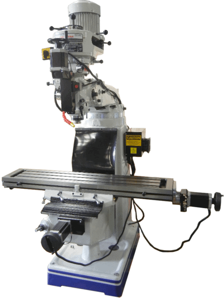
The CNC Supra is easy to learn and operate. The Supra 9 x 49 is your classic vertical knee milling machine with CNC technology. It features heavy-duty All Cast Iron construction and full three axis interpolated movement with computer variable spindle control put it a step above many other milling machines. The Supra 9 x 49 Mill handles max travel of 34” x 11.5” on the X and Y axis, while the Z axis is quill driven for accuracy. Supra mills are capable of manual/conventional control as well as CNC control.
It is considered among the leading vertical milling machines on the market.
Conclusion
This list isn’t exhaustive by any means and can be adapted for most other machine shop cutting tools, from a drill press to a router. Some can also be modified for woodworking projects – although the focus here has been on metalworking machinists.
Regardless, whether you’re a hobbyist or professional, these mini mill projects are fantastic places to start your CNC lathe or mini mill experience.


