


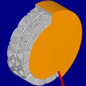
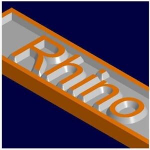
CAD-CAM software is an integral part to any CNC mill and lathe. These days just about every manufacturing plant, R & D lab, and engineering consultants use CAD to draw out their particular application in 2D and 3D formats or they will not be able to compete in this market.
If you have a CAD (Computer Aided Drafting) software that you use and it can generate a file with these any of these extensions (dwg, dxf, igs, stl, stp), we can offer you a fantastic, CAM (Computer Aided Manufacturing) software that will convert your CAD file into a working tool path program that you can import into the MX software and machine your part.
We offer VisualCAD/CAM by Mecsoft which comes with a guaranteed post processor that will generate the right G-Codes for our CNC milling machines and CNC Lathes. Mecsoft provides excellent direct support and offers detailed tutorials to help you master how to use VisualCAD/CAM for your machining applications. VisualCAM Standard will be a worthy investment to generate your drawings into G-Codes. The Master MX Operating software, which automatically comes with your purchase of a CNC Masters machine, will read the G-codes and machine your part according to your drawing.
If you need a basic CAD to draw your applications, VisualCAD/CAM comes with the ability for you to draw your applications to be machined on a mill or lathe. A 4th axis option which upgrades your VisualCAD/CAM from Standard to Expert mode. The license is yours to keep, no monthly subscription. When you buy VisualCAD/CAM from CNC Masters your software package will also include first year maintenance. This maintenance plan includes phone, email and web-based access direct tech support. You can renew this Maintenance plan annually for a nominal fee. This will ensure that you will always receive the latest VisualCAD/CAM software every time along with that direct tech support that is difficult to obtain with other subscription based CAD-CAM platforms.
This is a general purpose machining program targeted at the general machinist. This product is ideal for the rapid-prototyping, hobby and educational markets where ease of use is a paramount requirement. Packed with sufficiently powerful manufacturing methods this easy to use package is not only effective but also attractively priced for the budget conscious or entry level buyer. This software is a Windows based friendly program and will requires a Windows 10 PC.
CAD Creation / Editing Tools
- 2D and 3D CAD Creation
- Layers
- Unlimited Undo
- Clipboard
- True Type Font Text
- Measuring Tools
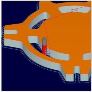
2 1/2 Axis Milling
- Pocketing
- Profiling
- Engraving
- Facing
- V-Carving
- Hole-Milling
- Thread Milling
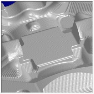
3-Axis Milling
- Horizontal Roughing
- Parallel Finishing
- Horizontal Roughing
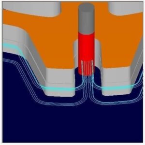
Hole Making
- Automatic Hole Selection, Sorting
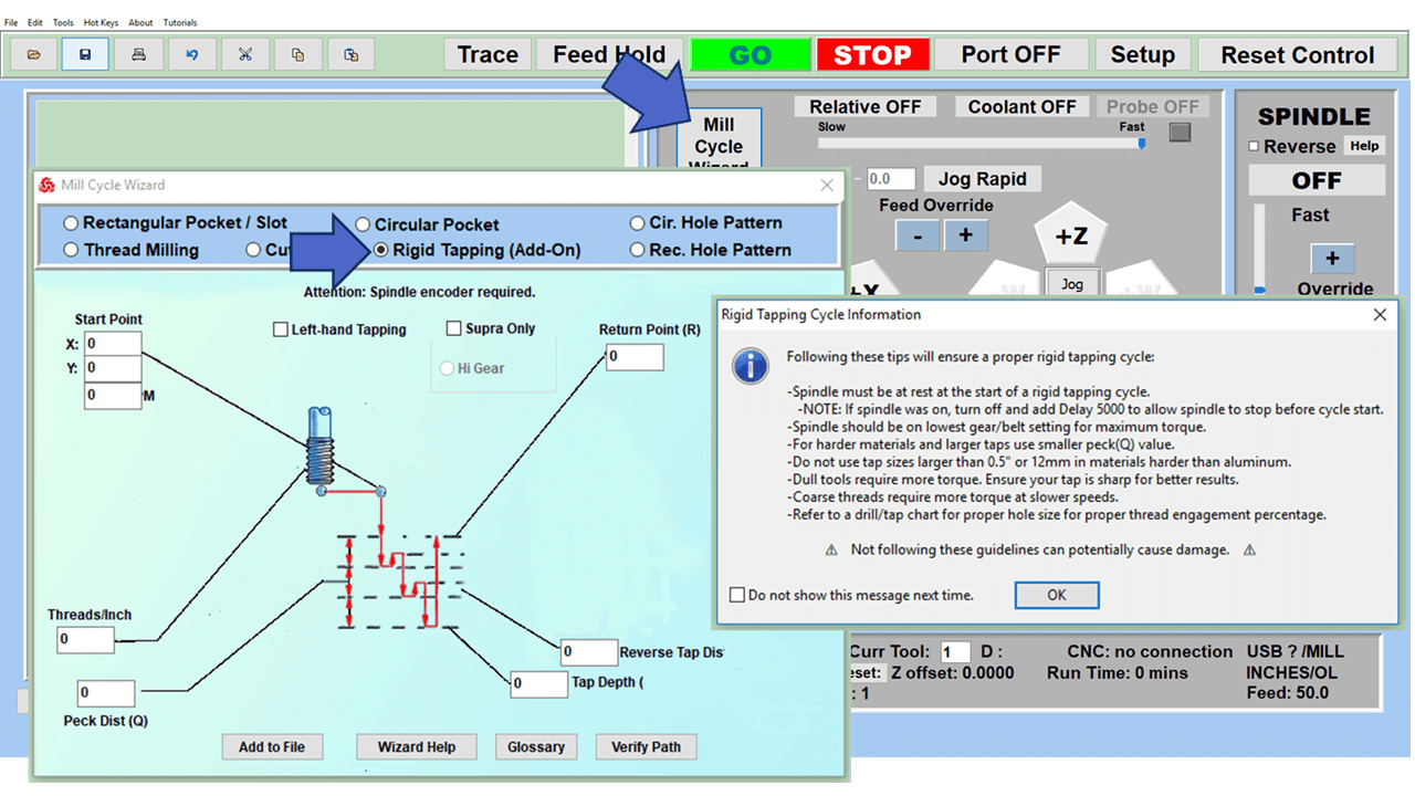
- Drilling
- Tapping
- Boring
- Reverse Boring
- User-defined drilling cycles
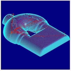
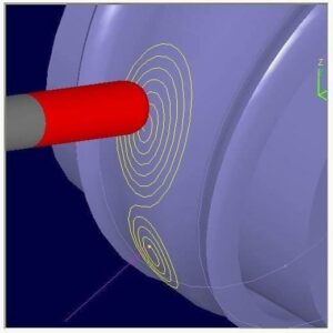
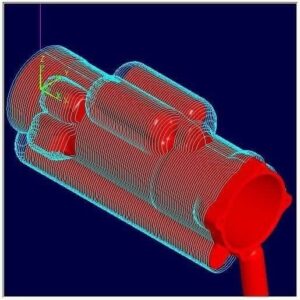
Toolpath Simulation
- Toolpath Animation
- Cut Material Simulation
Post-Processor Generator
- User customizable post-processor generator
- User defined cycles
- Helix Output
- Spiral Output
- Simulate Cycles
X-Pert DNC
- Direct numerical control
MetaCut Utilities
- G Code Analysis Verification Tool
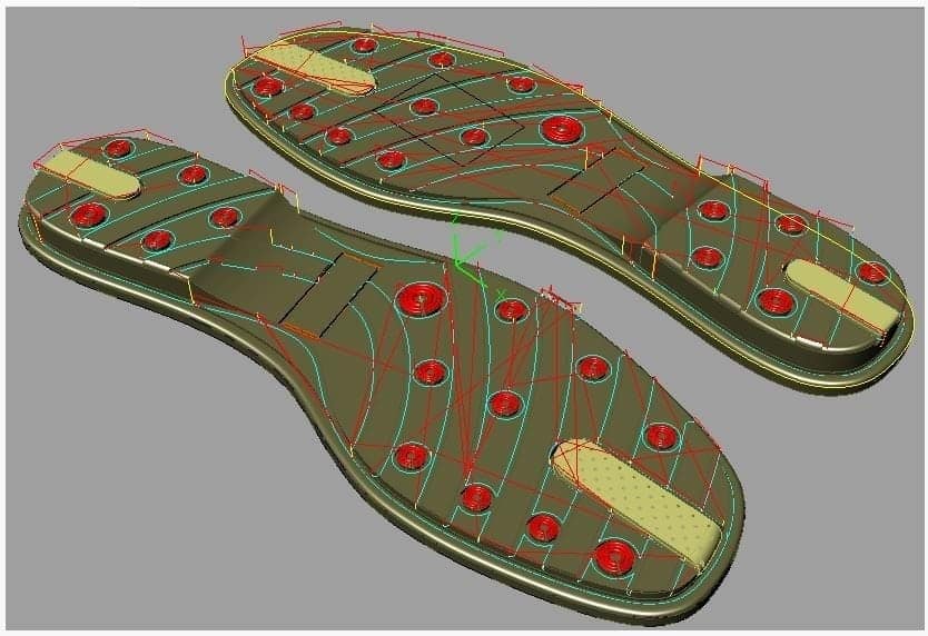
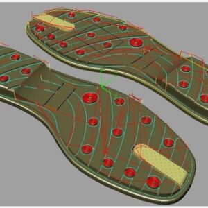
Lathe Applications – Turn Module
- 2 Axis Turning / Lathe tool path generation
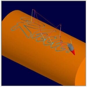
Art Module
- Artistic Modeling (Raster to Vector conversion)
- Pictures to 3D geometry
Nest Module
- Parts Nesting (Rectangular and True-Shape Nesting)
- Easily create a program to machine the same widget across the machine’s table on one program
4 Axis Milling (Add-On Expert Mode)
- 4-Axis Indexed Machining
- 4-Axis Continuous Rotary Machining
- 4-Axis Continuous Rotary Engraving
- 4-Axis Parallel Roughing
- Expert mode adds 4th Axis indexed and continuous roughing and finishing operations to VisualCAD/CAM STD. Curve based continuous machining such as 4 Axis Facing, Pocketing, Profiling & Engraving as well as Surface/solids/meshes based machining such as Roughing, Finishing and Curve Projection machining are available for your CNC Masters Milling Machine. The EXP configuration also includes TURN, NEST and ART modules free of cost! Needless to say, direct tech support is also included with your purchase. (Must be bundled with VisualCAD/CAM STD.)
First Year Maintenance Included
- When you combine your purchase with a CNC Masters Milling Machine or CNC Masters Lathe
- Direct tech support by phone, online connection, and email
- Tutorials, and updates
- You can opt to keep the maintenance package for a nominal annual subscription fee after your first year. If you choose not to keep this maintenance package, you still keep the license to your software.
Case Studies – Our customers using VisualCADCAM
- Click here: Cool Machining Job from Technology Patent
- Click here: Machining a Thermoplastic Heater Block in 2.5 Axis using VisualMILL


Reviews
There are no reviews yet.