CALL US TODAY

CALL US TODAY

fully assembled mini mill in toolroom

What is a Toolroom Mill? Everything You Need to Know

In many manufacturing facilities, the toolroom is an area, usually segregated from production, where tools such as jigs, fixtures, and dies are stored. Itā€™s also where these tools are inspected and repaired when they are returned after a production run.

The tools referred to in this context are typically not hand tools but expensive, complex assemblies installed into production machinery on the shop floor. Examples of these tools include a progressive stamping tool and die set to form metal parts and a mold assembly for plastic injection molding.

Since these dies and fixtures sustain normal wear and tearā€”and sometimes accidental damageā€”they must be repaired or replaced occasionally. For those operations, machine tools are placed within the toolroom, and specially trained machinists also called tool and die makers, perform the repairs or produce replacement parts using these machines.

There will undoubtedly be at least one toolroom mill among the machines in the toolroom, including a lathe, saw, and grinder. Here is what makes it unique.

What is a Toolroom Mill and What Sets it Apart?

A toolroom mill is a milling machine, although usually smaller and more compact. Toolroom mills produce precision work on a reduced scale: typically one-off parts similar to a job shop that creates prototypes. These machines could be standard milling machines or small vertical machining centers (VMC) complete with an automatic tool changer (ATC).

Many smaller shops prefer a standard-sized toolroom milling machine so they can use it as a backup for operations unrelated to the toolroom. The ideal solution for these shops is a space-saving CNC knee mill that quickly converts to a standard mill while retaining the functionality of a full CNC model.

Although Haas CNCs, with their TM-2P and TM-3P models, have name recognition, a better candidate for a CNC toolroom mill comes from an American-made brand: CNC Masters, a leader in desktop CNC machines. They offer manual and CNC mode in one machine tool and plenty of features to qualify it as a CNC toolroom mill. Look at the following important toolroom mill features; the CNC Masters mills have every one of them.

What are the Essential Features Specific to a Toolroom Mill?

As you shop for a toolroom mill, remember the space you can allow for it, the type of work you anticipate, and who will operate it. Then, look for these features:

  • Small footprint: Working within the confines of a toolroom, these milling machines are typically compact, large enough to handle the bulkiest jigs, fixtures, and dies but nothing more significant. Vertical knee and benchtop mills generally occupy significantly less space than bed mills.
  • Precision: Tool and die work requires precision, so you need a machine tool that consistently holds tight tolerances. Although a toolroom mill can fill in on production work, that isnā€™t its primary function.
  • Affordability: Even though toolroom mills are precision machine tools, they are affordable for minor operations. For example, CNC Masters offers their CNC Baron, an efficient and compact cast iron milling machine, for a starting price under $6,500.
  • Flexibility: Sometimes, you need a 3-axis CNC for complex fixtures and molds, while at other times, you merely want to hop on a manual mill for a tapped hole or quick slot. The option of manual or CNC mode in one machine tool makes a machinist much more productive.
  • Shallow learning curve: Your CNC toolroom mill should be easy for any beginner or experienced machinist to learn and operate.
  • Capable of 4th-axis CNC: Besides the X and Y-axis table movements and the Z-axis quill and knee movements, a 4th-axis rotary table offers even more options for machining complicated parts.
  • Coolant base: Directing coolant at the cutting tool when machining the tough material used on dies and fixtures keeps the temperature in check, prevents tool failure, and washes the chips away from the part.
  • Taper spindle: The R8 taper, found on Bridgeport-type mills, gives you a more comprehensive selection of tooling, such as end mills and chucks, typically at a lower price.
  • Conversational programming with G-Code: Conversational CNC is programming G-code by asking the programmer questions to create operations similar to those a manual machinist might use. It is an option built into many CNC controls.

Do the New Breed of Mini-Mills Qualify as Toolroom Mills?

CNC mini-mills meet all the criteria for a toolroom mill, especially the tiny footprint, and affordability. However, the determining factor is whether the size of the worktable and its travel limits are substantial enough for the work you have in mind.

max cnc mill
The Max CNC Mill

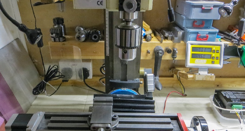
For instance, the CNC Max Tabletop Milling Machine from CNC Masters has 21.5ā€³ of X-axis travel and 10.5ā€ on the Y-axis. A 2-horsepower motor generates 4,500 RPMs, while ball screws on all three axes provide precision and accuracy. The machineā€™s head tilts for angled drilling, horizontal milling, slotting, and more.

The MAX CNC Mill has a cast-iron body, sliding dovetail ways, and tapered gibs on the square column for accuracy, repeatability, and alignment. It is a versatile benchtop CNC mill offering primary or secondary CNC machining applications. And you can add a fourth axis to machine cylindrical parts such as gears, fan blades, and splines.

You get all this for under $6,000!

Advantages and Disadvantages of Toolroom Mills

A toolroom mill has advantages over a full-size milling machine, but there are also some disadvantages.

Toolroom Mill Pros

  • Cost: You can purchase a new CNC mini-mill for under $6,000 or a compact toolroom CNC knee mill starting at $12,500. Thatā€™s a fraction of the price of a new full-sized milling machine at $100,000 and up
  • Technology: For CNC mini-mill and vertical knee mill prices, you get a boatload of technology, especially if your package comes with CAD/CAM software
  • Size: Another benefit of the mini-mill or the knee mill is its small footprint. Mini-mills fit on a desktop or bench, often called ā€œdesktopā€ or ā€œbenchtopā€ mills. Bridgeport vertical knee mills take up little space and fit comfortably in the corner of the toolroom.

Toolroom Mill Cons

  • Size: Yes. The size of a compact toolroom mill can also be a disadvantage if you must repair or produce a part that doesnā€™t fit on the worktable. The machine is too small for some parts, and you could experience rigidity issues on more challenging materials
  • Capability Problems: You may not be able to take deep cuts on carbon or stainless steel with most mini-mills because they are not as rigid as a full-sized machining center. Many are designed to machine plastics, wood, and soft metals like copper and aluminum. On the other hand, CNC knee mills do pretty well with roughing and hogging operations

An Example of the Ideal Toolroom Mill

CNC Supra knee mill
CNC Supra ā€“ A perfect toolroom knee mill

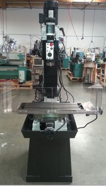
Considering the best features of a toolroom mill, is there a specific machine tool meeting all the criteria with few or none of the disadvantages? The good news is that one CNC milling machine has all the best features of a toolroom mill: the CNC Supra Vertical Knee Mill from CNC Masters.

With a 62.5ā€ x 57ā€ footprint, the Supra is a compact and versatile mill capable of CNC or manual control. Repeatability within 0.0005ā€³ defines the Supra as a precision machine worthy of the tight tolerances of toolroom applications. Easy to learn and operate, the Supra starts at $12,500, and for an additional $1,500, you can add a rotary table and have a 4-axis machine.

If you have questions, please email us directly at sales@cncmasters.com or call us at 626-962-9300. You can also visit our facility in Irwindale, CA. Please get in touch with us for an appointment, so we can give you our undivided attention and ensure we have a machine up and running for your visit.

Featured image courtesy of Tudor BarkerĀ 

About Peter Jacobs

Peter Jacobs is the Senior Director of Marketing at CNC Masters, a leading supplier of CNC mills, milling machines, and CNC lathes. He is actively involved in manufacturing processes and regularly contributes his insights for various blogs in CNC machining, 3D printing, rapid tooling, injection molding, metal casting, and manufacturing in general. You can connect with him on his LinkedIn.

Have Questions? Need a Quote?

Looking for more information about our CNC machines and services? Contact us today.

Contact

Slide 1

29. Create a Peck Drilling Program in Circular or Rectangular Patterns
Using the Circular or Rectangular Drilling Wizards, you can program the machine to drill an un-limited series of holes along the X and Y planes. Program it to drill straight through to your total depth, use a high-speed pecking cycle, or deep hole pecking cycle. You can program the cut-in depth and return point for a controlled peck drill application to maximize chip clearance.

Slide 1

20. Change up to 30 tools with compensation, and store your tool offsets for other programs
The MX supports…

Slide 1

21. Use the optional ATC rack up to 8 tools for milling, drilling, and rigid tapping applications
The CNC Masters Automatic Tool Changer Rack and Tools (US Patent 9,827,640B2) can be added to any CNC Masters Milling Machine built with the rigid tapping encoder option. The tutorial will guide you through the set-up procedure using the ATC tools.

Slide 1

22. Use the optional Rigid Tapping Wizard without the need for tapping head attachments
When you order your CNC Masters machine, have it built with the optional rigid tapping encoder. You can take any drill cycle program and replace the top line with a tapping code created by the wizard to tap your series of holes up to 1/2ā€ in diameter.

Slide 1

23. Use the optional Digital Probe to scan the profile and/or pockets of your fun/hobby type designs to write your tool path program and machine out a duplicate of your original design To ā€œsurfaceā€ scan an object, you can program the probe along the X or Y plane. The stylus will travel over the part starting on the left side front corner of the object and work its way to the end of the part on the right side. Depending on how the stylus moves, it will record linear and interpolated movements along the X, Y, and Z planes directly on the MX Editor.
To ā€œpocketā€ scan an object containing a closed pocket such as circles or squares, the scan will start from the top front, work its way inside of the pocket, and scan the entire perimeter of the pocket.
Under the Setup of the MX software you will find the Probe Tab which will allow you to calibrate and program your probe. Your ā€œProbe Stepā€, ā€œFeedā€, and ā€œData Filterā€ can also be changed on the fly while the probe is in the middle of scanning your object.

Slide 1

24. Use work offsets G54-G59 for nesting applications
The work offsets offer you a way to program up to six different machining locations. Itā€™s like having multiple 0.0 locations for different parts. This is very useful especially when using sub-routines/nesting applications.

Slide 1

25. Create a Rectangular Pocket / Slot with our selection of Wizards to help you build a tool path program
The Cycle Wizards for the mill or lathe makes it easy to create a simple tool path without needing to use a CAD and CAM software.
On this Wizard, the Rectangular Pocket / Slots, can be used to form a deep rectangular pocket into your material or machine a slot duplicating as many passes needed to its total depth.

Slide 1

26. Create a Circular Pocket Wizard
Input the total diameter, the step down, and total depth and the code will be generated.

Slide 1

27. Do Thread Milling using a single point cutter Wizard

Slide 1

28. Cut a gear out using the Cut Gear Wizard with the optional Fourth Axis

Slide 1

19. Disable the axis motors to manually hand crank each axis into place
Easily de-energize the axis motors by clicking [Disable Motors] to crank each axis by hand, and then press [Reset Control] to re-energize the axis motors.

Slide 1

30. The MX interface can easily be interchanged from Mill Mode to Lathe Mode
Use this interface for your CNC Masters Lathe. It contains all the same user-friendly features and functions that comes in Mill Mode. Simply go to the Setup page and change the interface.

Slide 1

31. Use Tool Change Compensation or the optional Auto Tool Changer Turret if your application requires more than one tool in a single program
You can offset the length and angle of each tool and record it under Tools in your Setup. The program will automatically pause the latheā€™s movement and spindle allowing you to change out your tool, or allowing the optional ATC Turret to quickly turn to its next tool and continue machining.
On the MX interface, you also have four Tool Position buttons. Select your desired T position, and the auto tool post will quickly turn and lock itself to that position.

Slide 1

32. Use the Lathe Wizard Threading Cycle to help you program your latheā€™s internal or external threads in inches or metric

Slide 1

33. Use the Lathe Wizard Turning / Boring Cycle to help you program simple turning and boring cycles without having to go through a CAM or writing a long program with multiple passes

Slide 1

34. Use the Lathe Wizard Peck Drilling Cycle to help you program your drill applications or for face grooving

Slide 1

35. Facing / Grooving / Part Off Cycle Wizards ā€“ with Constant Surface Speed
These cycles can be used with Constant Surface Speed allowing the spindle speed to increase automatically as the diameter of the part decreases giving your application a consistent workpiece finish. With CSS built into the wizard, there is no need to break down the cycle into multiple paths and multiple spindle speed changes.

Slide 1

36. This is our list of supported G and M codes which can be found under Tools > G Code/ M Code List in the MX
If you plan to use a third-party CAM software to generate your tool path program, use a generic FANUC post processor and edit it to match our list of codes. As an option, we also sell Visual mill/turn CAM software which comes with a guaranteed post processor for our machines to easily generate your tool path programs based on your CAD drawings.

Slide 1

37. Our pledge to you…

Slide 1

10. Run each tool path independently to study its movement
1. Run the machine on Trace mode. You can run each tool path independently, one line at a time to study the tool path movement on the machine to verify the position of the application and if any fixture/vise is in the way of the cutterā€™s path.

2. You can also verify your program by clicking on the Trace and Draw buttons together. This will allow you to view each tool path independently one line at a time in the Draw Window.

Slide 1

2. Clutter Free Interface
The MX is engineered for the CNC MASTERS machine so you do not have to fiddle with a detailed complicated configuration that can be overwhelming. Just load in the MX and start machining!2. Clutter Free Interface
The MX is engineered for the CNC MASTERS machine so you do not have to fiddle with a detailed complicated configuration that can be overwhelming. Just load in the MX and start machining!

Slide 1

3. Features Tour and Tutorials Included
The Features Tour will give you a quick run-down on all the features the MX can do for you. The Tutorials are easy to follow even for the first time CNC machinist.
Feel free to download the MX on any of your computers. We recommend downloading the MX along with your CAD and CAM software there at the comfort of your office computer to generate your tool path programs. You donā€™t need to be hooked up to the machine either to test your program in simulation mode.

Slide 1

4. Navigate and Edit Your Program through the MX interface with Ease
With a few clicks of the mouse or using touch screen technology, you can easily navigate through the MX interface importing saved programs into the Editor from the File drop down menu. Using standard windows features to edit your program you can then lock the Editor Screen to avoid accidental editing, and if you need to insert a line in the middle of a program, just click on [ReNum] to re-number your tool path list.
You can create a program or import CAM generated G-code tool paths into the Editor
The X Y and Z W arrow jog buttons are displayed from the point of view of the cutter to avoid confusion when the table and saddle are moving. You can also adjust your spindle speed and coolant control while jogging each axis.

Slide 1

5. Feed Hold ā€“ Pause in the Middle of your Program
Feed Hold lets you pause in the middle of a program. From there you can step through your program one line at time while opting to shut the spindle off and then resume your program.
You can also write PAUSE in the middle of your program and jog each axis independently while your program is in pause mode.

Slide 1

6. Hot Keys
Hot Keys is an alternative method to easily control your machine using your hard or touch screen keyboard. One can press P to pause a program, press S to turn Spindle On, G to run a program, Space Bar to Stop, J to record your individual movements one line at a time to create a program in teach mode.

Slide 1

7. Pick Menu ā€“ for conversational mode programming
Write FANUC style G-codes directly into the Editor or select commands off the [Pick] menu and write your tool path program in conversational mode such as what is written in the Editor box. You can even mix between conversation commands and G-codes in the same program.

Slide 1

8. Pick Menu List of Options
Use commands such as MOVE, SPINDLE ON/OFF, COOLANT ON/OFF, PAUSE, DELAY, GO HOMEā€¦. to write your tool path programs in conversational mode.

Slide 1

9. Draw the Tool Path to verify it before pressing Go
Hit Draw to view your tool path program drawing, check out its run time, or even simulate the tool path in 3D mode. This can be helpful to quickly verify your program before running it. You can also slow down or speed up the drawing or simulation process.
You can also hit Go within the Draw Window itself to verify the cutterā€™s position on the machine. The current tool path will be highlighted and simultaneously draw out the next path so you can verify what the cutter will be doing next on the program.

Slide 1

MX Software ā€“ Easy to Use, Easy to Learn ā€“ Included with your machine purchase
The MX software is designed to work seamlessly with your CNC Masters machine. It is made to work with Windows PC ā€“ desktop, laptop, or an all in one ā€“ on standard USB. Use it on Windows 8 or 10 64-bit operating systems.
No internal conversion printer/serial port to USB software or additional conversion hardware is used with the MX.

Slide 1

11. Counters display in Inches or Millimeters ā€“ Continuous Feed
1. When running a program, the counters will display a ā€œreal-timeā€ readout while the machine is in CNC operation without counting ahead of the movement.
2. The current tool path is highlighted while the machine is in operation without causing slight interruptions/pauses as the software feeds the tool path to the machine. The MX internally interprets a program ten lines ahead to allow for ā€œcontinuous machiningā€ avoiding slight interruptions as the machine waits for its next tool path command.
3. ā€œRun Timeā€ tells you how long it takes to run your tool path program.

Slide 1

12. Use the ā€œGo From Lineā€ command to start in the middle of your program
If you ever need to begin your program from somewhere in the middle of it, use [Go From Line] which you can find under Tools. The Help guide will walk you through how to position the cutter without losing its position on the machine.

Slide 1

13. Exact Motion Distance without over-stepping on an axis while jogging
Use ā€œRelative ONā€ to enter a specific coordinate to jog any of your axes to an exact location without having to write a program. Itā€™s like using ā€œpower feedā€ but easier. You can jog an exact distance on any of the axes without needing to keep the key pressed down and mistakenly over-step the movement releasing your finger too slowly off the jog button.
Letā€™s say you need to drill a hole exactly 0.525ā€ using the Z. So you enter 0.525 in the Z box. Next, adjust the JOG FEED RATE slider for the desired feed rate. Then ā€œclick onceā€ on the +Z or -Z button to activate the travel. In this case you click once the -Z button first to drill the hole exactly 0.525ā€. Then click once on the +Z button to drive the axis back up 0.525ā€.

Slide 1

14. Teach Mode ā€“ Jog Input
You can create a tool path program by storing each point-to-point movement by simply jogging an axis one at a time. Click on either of the Jog Input buttons to store each movement on the Editor Screen. You can then add Spindle ON, feed commands, and press GO to run the new program as needed. This is a great feature to help you learn to create a program by the movements you make on the machine without necessarily writing out an entire program first.

Slide 1

15. Override on the fly to adjust the Jog Feed to Rapid or the Spindle Speed during the middle of a program
1. Jog Feed and Rapid with Override: You can adjust feeds using the slider from slow minimum 0.1ā€³ per minute to a rapid of 100ā€³ per minute of travel. You can even micro-step your jog as low as 0.01ā€/min. The [-][+] buttons allow you to fine tune feeds in 5% increments while the program is in motion.
2. Spindle Speed with Override: You can adjust speeds using the slider from a slow minimum RPM to the max RPM according to the machine setup. The [-][+] buttons allow you to fine tune feeds in 5% increments while the program is in motion.

Slide 1

16. Adjust Counters using Pre-Set if you cannot begin the program from 0.00
In a situation where you cannot begin your cutter at itā€™s 0.00 location, you can ā€œPre-Setā€ directly into the counters by typing in your beginning coordinate. You can press Go from here to run your program. You can also ā€œzero allā€ or ā€œzeroā€ your counters independently. With one click of the [Return to 0.0] button, all axes will travel back to its respective 0.0 on the machine.

Slide 1

17. Set and Save your 0.00 position for future runs
Set and save your 0.00 position on the machine. These coordinates will be recorded as the first line of the program in the Editor Screen. Should you desire to return to this program at a later date, you only have to click on the Set Zero Return button. This will command the machine to automatically jog each axis to its saved ā€œsetā€ 0.00 position according to the recorded coordinates at the first line of the program.

Slide 1

18. Create a ā€œHomeā€ position to clear your application and run multiple times
Letā€™s say you need to machine one application times 100 pieces. This usually requires a jig to retain that physical 0.00 position. But in this case, you want the program to end with a clearance of the axes to easily switch out the next piece of stock and start again. With Save Home, you have the ability to save this offset (home) position while still retaining your Set Zero position where the machine will mill your part out. Pressing [Save Home] will record this new position under the Set Zero line in your program.
Pressing [Go Home] will jog your axes back to your ā€œsaved homeā€ position where you originally pressed the Save Home command. You can also input GO_HOME from the Pick Menu as its own tool path in your program. At the completion of your program the axes will end at your Home position. Replace your part, then press [Return to 0.0] button to allow the axes to return to its zero position, and press Go to start your next run.

previous arrow
next arrow