CALL US TODAY

CALL US TODAY

home milling machine cutting wood

9 Features the Best Home Milling Machines All Have

Many skilled machinists have joined the hobbyists in setting up small DIY shops in their garages and home workshops. In most cases, the milling machine is the machine tool of choice over the lathe primarily because of its versatility. However, the term ā€œmilling machineā€ covers a lot of territory, so make sure you choose the best milling machine for your needs.

vertical milling machine diagram
1. Face milling cutter – 2. Spindle – 3. Spindle head – 4. Column – 5. Table – 6. Saddle – 7. Knee – 8. Base – 9. Spindle switch – 10. Spindle speed gear lever – 11. Spindle speed control level – 12. Oil tank – 13. Table manual wheel – 14. Table lock bar – 15. Saddle automatic moving bar – 16. Saddle automatic moving control dial – 17. Saddle manual wheel – 18. Knee manual wheel – 19. Quick button

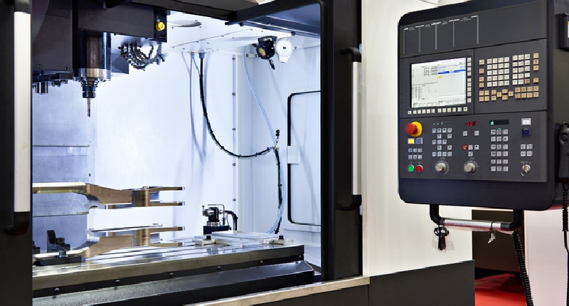
There are two basic types of milling machines: vertical milling machines and horizontal milling machines. Since horizontals are typically large and targeted for specific types of work, they lack the versatility and compact design of the vertical milling machine, leaving you with two options: a Bridgeport-type milling machine and a benchtop milling machine, also known as a mini milling machine.

As we consider the features that high-quality milling machines should have to earn a place in your garage or workshop, letā€™s make two assumptions. First, whether youā€™re a seasoned machinist working for a living or a hobbyist creating art, you care about quality and take pride in your creations. Second, you want to use your milling machine to produce pieces that occasionally (or frequently) demand some degree of complexity.

With those suppositions in mind, here are the nine features to look for in your next home milling machine:

1. Make Sure Your Machine Tool Has CNC Milling Capabilities

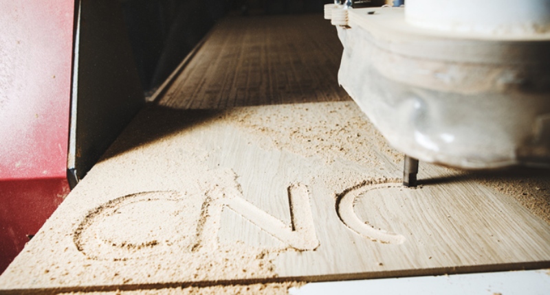
Computerized Numerical Control, or CNC milling, is the modern method of completing woodworking and metalworking tasks in the home shop. Using Computer-Aided Design (CAD) and Computer-Aided Machining (CAM) software, CNC milling has supplemented or replaced manual milling machines like the classic Bridgeport Mill, even in the garage and workshop.

CNC machines have become the choice of hobbyists, schools, and self-employed machinists for various reasons: CNC machines are faster and more accurate, but even if youā€™re a hobbyist who isnā€™t concerned about high-speed machining and tight tolerances, a CNC milling machine can produce complex shapes that are practically impossible on a traditional milling machine.

If you have a customer requiring dimensional accuracy, your CNC mill will provide it, and if you have multiple parts to manufacture, each one of them will be as precise as the first one. This repeatability feature of CNCs cannot be overstated: if you are hoping to compete in industries such as aerospace, medical, or the military, accuracy, and repeatability are essential.

And if youā€™re a hobbyist or machinist interested in doing customized work, your CNC machine tool will make that possible. In other words, if you are serious about what you produceā€”whether practical or artisticā€”CNC capability is the first feature to insist upon.

2. The CNC Mill Should Be Easy to Learn and Operate

Hobbyists and self-employed machinists working in a home shop might be intimidated by the mere thought of owning a CNC vertical milling machine. They envision steep learning curves with unfathomable computer jargon, but nothing could be farther from the truth.

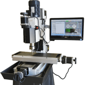
High-quality American-made CNC mills from companies like CNC Masters include comprehensive, user-friendly guides to ensure a smooth setup and manageable steps. Most CNC machines, especially the smaller benchtop and Bridgeport-style models, are designed with ease of operation in mind so that learning G-code and the fundamentals of CNC programming and milling is not an overwhelming challenge.

The CNC mills work seamlessly with your computer and a single-phase hook up, so you can master the software quickly and realistically be making chips relatively soon after you set your CNC mill in place on your workbench or floor.

3. Home Milling Machines Should Have a Compact Design

max cnc home milling machine
The CNC Max Home Milling Machine

The idea of having a home milling machine is to conduct a business or hobby in the limited work area of the typical workshop or garage. However, before you rush out and buy the smallest, space-saving micro mill on the market, consider the type of work you are proposing to pursue.

Make sure the CNC machine you purchase can handle the workpieces and that it is powerful enough to cut materials such as cast iron and stainless steel if thatā€™s whatā€™s required. Although saving precious floor space is important, it does not outweigh the need to have a CNC mill with a worktable suitable for the sizes youā€™ll be machining and enough horsepower to drive the cutting tools youā€™ll use to get the job done.

4. Versatility is the Key to the CNC Home Milling Machine

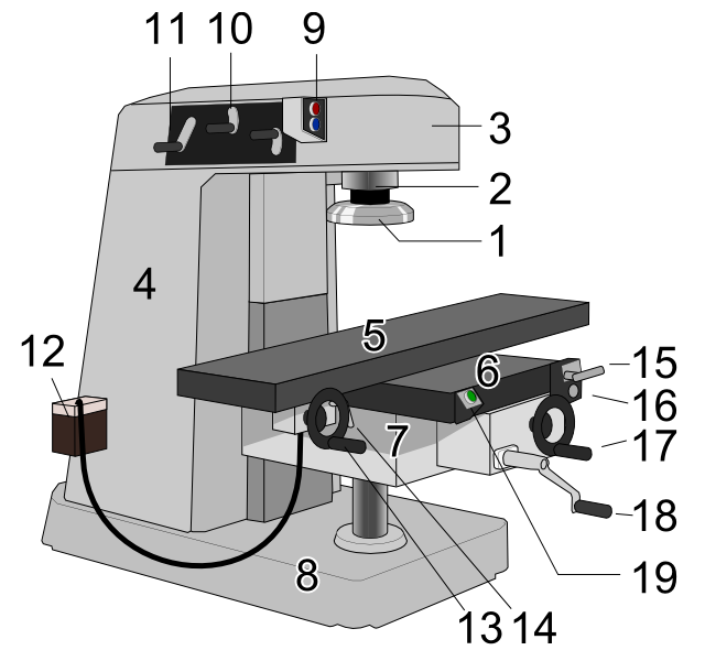
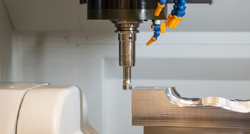
A CNC vertical milling machine can perform so many tasks that calling it versatile seems somewhat inadequate. You can use them to produce flat surfaces with a face mill or irregular surfaces and slots with various end mills. Add a drill chuck or collets into the R8 spindle taper within the headstock, and you have a heavy-duty, variable-speed drill press.

You can machine custom work, engraving, production parts, or prototyping. Add a vise to the worktable for smaller parts or clamp larger workpieces directly to the worktable. With variable spindle speeds, you can use it as a drilling machine for tapping and boring holes or to cut gear teeth as a milling machine. And with an optional digital readout (DRO), you can determine precise locations for all those holes and slots.

Depending on the type and size of the material, you can turn your CNC milling machine into a CNC router. Or you can transform your CNC mill into a Bridgeport-type manual mill when you have only one or two simple parts to knock out. Handwheels on the X-axis and Y-axis and power feed make the conversion immediate, and just as quickly, it returns to being a CNC mill.

Engineers, research institutions, trade schools, high schools, universities, hobbyists, and home shop machinists all marvel at and take advantage of the versatility of the many variations of the CNC milling machine.

home milling machine cutting wood
A milling machine cutting wood

5. Home CNC Milling Machines Feature Flexibility

CNC mills give machinists and hobbyists options in materials which, in turn, opens a wide range of DIY projects for them. They can choose from various metals, plastics, wood, composites, etc. for their workpiece, allowing them to create complex designs or take on production runs.

Although manual milling machines still have a purpose in a manufacturing facility, CNC mills expand the possibilities in areas once reserved for the big guys. That leveling of the playing field means a one-man shop can compete with any large company on parts that will fit on a CNCā€™s worktable. Thatā€™s exciting news!

large milling machine
CNC milling machines are versatile. Some are compact and perfect for home, while others are large and better suited to industrial shops

6. Automation is Another Top Feature of the CNC Mill

The home machinist or hobbyist would be tied to a manual machine throughout the day without the ability to perform customer service and work on quotes without shutting down the machine and jeopardizing promised deliveries and profits.

CNC machines change that by allowing the CNC machinist in a one-person shop to work on the business, while a programmed CNC mill works in the business at the same timeā€”all without adding an operator. Depending on the length of the program, itā€™s possible to set up and start a run, watch your daughterā€™s softball game, for instance, and be back in time to load a fresh workpiece.

7. Full 3-Axis Coordinated Motion Control on Bipolar Motors

home cnc milling machineHigh-quality CNC milling machines feature multi-axis drives enabled by multi-axis controllers. They can perform at higher levels than single-axis distributed drives, and the bipolar motors have more torque and are more efficient. Together they provide accurate interpolationā€”typically linear and circularā€”guiding the CNC machineā€™s cutting tools to produce shapes through the simultaneous action of the x-axis, y-axis, and z-axis.

8. The Best CNC Milling Machines Feature Zero-Backlash Ball Screws

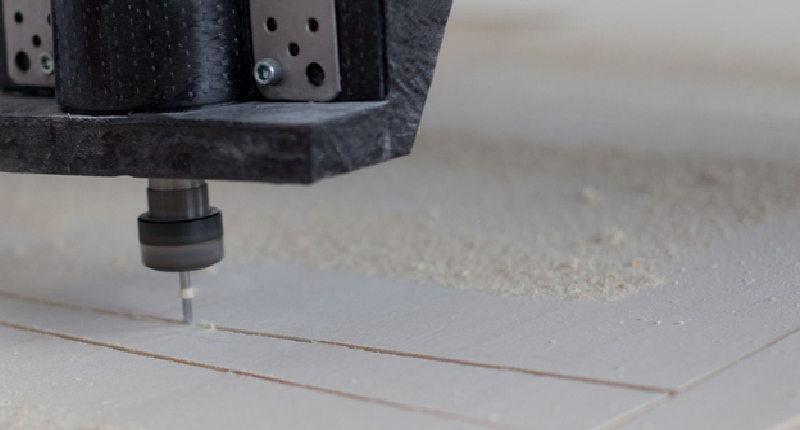
X, Y, and Z-axis zero backlash ball screws with pre-loaded ball nuts eliminate play on the table, saddle, and quill travel, enabling the milling head to provide accurate machining down to /- 0.00025 inch. Precision ball screws allow for close-tolerance conventional and climb milling operations and precise circular and contour cuts without time-consuming setups.

9. Ensure That Your New CNC Mill Has an Excellent Warranty and Service

Itā€™s no secret you can pick up a Wen, Grizzly, or Jet JMD mini-milling machine at Amazon. Or you can purchase one of CNC Mastersā€™ stand-alone or benchtop CNC millsā€”all built in the USAā€”and backed by the CNC Masters One-Year Warranty that you can extend to two years.

Youā€™ll also receive:

  • Unlimited ā€œLife-Longā€ Tech Support with step-by-step troubleshooting and walk-through process at sales@cncmasters.com or 626-962-9300 Monday-Friday during regular business hours (Pacific Time) for as long as your company owns the machine. (Nominal fee for second-hand owners.)
  • Unlike costly servo systems, CNC Masterā€™s lineup of high-quality CNC Vertical Milling Machines is easy to repair, replace parts, and maintain.
  • Free MX Operating Software Updates for original owners as long as the hardware can support it.

Deal Directly with the CNC Vertical Milling Machine Experts

Donā€™t compromise! Contact the pros at CNC Masters for the best home milling machines with all the features to enhance the experiences of machinists and hobbyists. Top-notch service and an iron-clad warranty is included with each of our excellent machine tools!

About Peter Jacobs

Peter Jacobs is the Senior Director of Marketing at CNC Masters, a leading supplier of CNC mills, milling machines, and CNC lathes. He is actively involved in manufacturing processes and regularly contributes his insights for various blogs in CNC machining, 3D printing, rapid tooling, injection molding, metal casting, and manufacturing in general. You can connect with him on his LinkedIn.

Have Questions? Need a Quote?

Looking for more information about our CNC machines and services? Contact us today.

Contact

Slide 1

29. Create a Peck Drilling Program in Circular or Rectangular Patterns
Using the Circular or Rectangular Drilling Wizards, you can program the machine to drill an un-limited series of holes along the X and Y planes. Program it to drill straight through to your total depth, use a high-speed pecking cycle, or deep hole pecking cycle. You can program the cut-in depth and return point for a controlled peck drill application to maximize chip clearance.

Slide 1

20. Change up to 30 tools with compensation, and store your tool offsets for other programs
The MX supports…

Slide 1

21. Use the optional ATC rack up to 8 tools for milling, drilling, and rigid tapping applications
The CNC Masters Automatic Tool Changer Rack and Tools (US Patent 9,827,640B2) can be added to any CNC Masters Milling Machine built with the rigid tapping encoder option. The tutorial will guide you through the set-up procedure using the ATC tools.

Slide 1

22. Use the optional Rigid Tapping Wizard without the need for tapping head attachments
When you order your CNC Masters machine, have it built with the optional rigid tapping encoder. You can take any drill cycle program and replace the top line with a tapping code created by the wizard to tap your series of holes up to 1/2ā€ in diameter.

Slide 1

23. Use the optional Digital Probe to scan the profile and/or pockets of your fun/hobby type designs to write your tool path program and machine out a duplicate of your original design To ā€œsurfaceā€ scan an object, you can program the probe along the X or Y plane. The stylus will travel over the part starting on the left side front corner of the object and work its way to the end of the part on the right side. Depending on how the stylus moves, it will record linear and interpolated movements along the X, Y, and Z planes directly on the MX Editor.
To ā€œpocketā€ scan an object containing a closed pocket such as circles or squares, the scan will start from the top front, work its way inside of the pocket, and scan the entire perimeter of the pocket.
Under the Setup of the MX software you will find the Probe Tab which will allow you to calibrate and program your probe. Your ā€œProbe Stepā€, ā€œFeedā€, and ā€œData Filterā€ can also be changed on the fly while the probe is in the middle of scanning your object.

Slide 1

24. Use work offsets G54-G59 for nesting applications
The work offsets offer you a way to program up to six different machining locations. Itā€™s like having multiple 0.0 locations for different parts. This is very useful especially when using sub-routines/nesting applications.

Slide 1

25. Create a Rectangular Pocket / Slot with our selection of Wizards to help you build a tool path program
The Cycle Wizards for the mill or lathe makes it easy to create a simple tool path without needing to use a CAD and CAM software.
On this Wizard, the Rectangular Pocket / Slots, can be used to form a deep rectangular pocket into your material or machine a slot duplicating as many passes needed to its total depth.

Slide 1

26. Create a Circular Pocket Wizard
Input the total diameter, the step down, and total depth and the code will be generated.

Slide 1

27. Do Thread Milling using a single point cutter Wizard

Slide 1

28. Cut a gear out using the Cut Gear Wizard with the optional Fourth Axis

Slide 1

19. Disable the axis motors to manually hand crank each axis into place
Easily de-energize the axis motors by clicking [Disable Motors] to crank each axis by hand, and then press [Reset Control] to re-energize the axis motors.

Slide 1

30. The MX interface can easily be interchanged from Mill Mode to Lathe Mode
Use this interface for your CNC Masters Lathe. It contains all the same user-friendly features and functions that comes in Mill Mode. Simply go to the Setup page and change the interface.

Slide 1

31. Use Tool Change Compensation or the optional Auto Tool Changer Turret if your application requires more than one tool in a single program
You can offset the length and angle of each tool and record it under Tools in your Setup. The program will automatically pause the latheā€™s movement and spindle allowing you to change out your tool, or allowing the optional ATC Turret to quickly turn to its next tool and continue machining.
On the MX interface, you also have four Tool Position buttons. Select your desired T position, and the auto tool post will quickly turn and lock itself to that position.

Slide 1

32. Use the Lathe Wizard Threading Cycle to help you program your latheā€™s internal or external threads in inches or metric

Slide 1

33. Use the Lathe Wizard Turning / Boring Cycle to help you program simple turning and boring cycles without having to go through a CAM or writing a long program with multiple passes

Slide 1

34. Use the Lathe Wizard Peck Drilling Cycle to help you program your drill applications or for face grooving

Slide 1

35. Facing / Grooving / Part Off Cycle Wizards ā€“ with Constant Surface Speed
These cycles can be used with Constant Surface Speed allowing the spindle speed to increase automatically as the diameter of the part decreases giving your application a consistent workpiece finish. With CSS built into the wizard, there is no need to break down the cycle into multiple paths and multiple spindle speed changes.

Slide 1

36. This is our list of supported G and M codes which can be found under Tools > G Code/ M Code List in the MX
If you plan to use a third-party CAM software to generate your tool path program, use a generic FANUC post processor and edit it to match our list of codes. As an option, we also sell Visual mill/turn CAM software which comes with a guaranteed post processor for our machines to easily generate your tool path programs based on your CAD drawings.

Slide 1

37. Our pledge to you…

Slide 1

10. Run each tool path independently to study its movement
1. Run the machine on Trace mode. You can run each tool path independently, one line at a time to study the tool path movement on the machine to verify the position of the application and if any fixture/vise is in the way of the cutterā€™s path.

2. You can also verify your program by clicking on the Trace and Draw buttons together. This will allow you to view each tool path independently one line at a time in the Draw Window.

Slide 1

2. Clutter Free Interface
The MX is engineered for the CNC MASTERS machine so you do not have to fiddle with a detailed complicated configuration that can be overwhelming. Just load in the MX and start machining!2. Clutter Free Interface
The MX is engineered for the CNC MASTERS machine so you do not have to fiddle with a detailed complicated configuration that can be overwhelming. Just load in the MX and start machining!

Slide 1

3. Features Tour and Tutorials Included
The Features Tour will give you a quick run-down on all the features the MX can do for you. The Tutorials are easy to follow even for the first time CNC machinist.
Feel free to download the MX on any of your computers. We recommend downloading the MX along with your CAD and CAM software there at the comfort of your office computer to generate your tool path programs. You donā€™t need to be hooked up to the machine either to test your program in simulation mode.

Slide 1

4. Navigate and Edit Your Program through the MX interface with Ease
With a few clicks of the mouse or using touch screen technology, you can easily navigate through the MX interface importing saved programs into the Editor from the File drop down menu. Using standard windows features to edit your program you can then lock the Editor Screen to avoid accidental editing, and if you need to insert a line in the middle of a program, just click on [ReNum] to re-number your tool path list.
You can create a program or import CAM generated G-code tool paths into the Editor
The X Y and Z W arrow jog buttons are displayed from the point of view of the cutter to avoid confusion when the table and saddle are moving. You can also adjust your spindle speed and coolant control while jogging each axis.

Slide 1

5. Feed Hold ā€“ Pause in the Middle of your Program
Feed Hold lets you pause in the middle of a program. From there you can step through your program one line at time while opting to shut the spindle off and then resume your program.
You can also write PAUSE in the middle of your program and jog each axis independently while your program is in pause mode.

Slide 1

6. Hot Keys
Hot Keys is an alternative method to easily control your machine using your hard or touch screen keyboard. One can press P to pause a program, press S to turn Spindle On, G to run a program, Space Bar to Stop, J to record your individual movements one line at a time to create a program in teach mode.

Slide 1

7. Pick Menu ā€“ for conversational mode programming
Write FANUC style G-codes directly into the Editor or select commands off the [Pick] menu and write your tool path program in conversational mode such as what is written in the Editor box. You can even mix between conversation commands and G-codes in the same program.

Slide 1

8. Pick Menu List of Options
Use commands such as MOVE, SPINDLE ON/OFF, COOLANT ON/OFF, PAUSE, DELAY, GO HOMEā€¦. to write your tool path programs in conversational mode.

Slide 1

9. Draw the Tool Path to verify it before pressing Go
Hit Draw to view your tool path program drawing, check out its run time, or even simulate the tool path in 3D mode. This can be helpful to quickly verify your program before running it. You can also slow down or speed up the drawing or simulation process.
You can also hit Go within the Draw Window itself to verify the cutterā€™s position on the machine. The current tool path will be highlighted and simultaneously draw out the next path so you can verify what the cutter will be doing next on the program.

Slide 1

MX Software ā€“ Easy to Use, Easy to Learn ā€“ Included with your machine purchase
The MX software is designed to work seamlessly with your CNC Masters machine. It is made to work with Windows PC ā€“ desktop, laptop, or an all in one ā€“ on standard USB. Use it on Windows 8 or 10 64-bit operating systems.
No internal conversion printer/serial port to USB software or additional conversion hardware is used with the MX.

Slide 1

11. Counters display in Inches or Millimeters ā€“ Continuous Feed
1. When running a program, the counters will display a ā€œreal-timeā€ readout while the machine is in CNC operation without counting ahead of the movement.
2. The current tool path is highlighted while the machine is in operation without causing slight interruptions/pauses as the software feeds the tool path to the machine. The MX internally interprets a program ten lines ahead to allow for ā€œcontinuous machiningā€ avoiding slight interruptions as the machine waits for its next tool path command.
3. ā€œRun Timeā€ tells you how long it takes to run your tool path program.

Slide 1

12. Use the ā€œGo From Lineā€ command to start in the middle of your program
If you ever need to begin your program from somewhere in the middle of it, use [Go From Line] which you can find under Tools. The Help guide will walk you through how to position the cutter without losing its position on the machine.

Slide 1

13. Exact Motion Distance without over-stepping on an axis while jogging
Use ā€œRelative ONā€ to enter a specific coordinate to jog any of your axes to an exact location without having to write a program. Itā€™s like using ā€œpower feedā€ but easier. You can jog an exact distance on any of the axes without needing to keep the key pressed down and mistakenly over-step the movement releasing your finger too slowly off the jog button.
Letā€™s say you need to drill a hole exactly 0.525ā€ using the Z. So you enter 0.525 in the Z box. Next, adjust the JOG FEED RATE slider for the desired feed rate. Then ā€œclick onceā€ on the +Z or -Z button to activate the travel. In this case you click once the -Z button first to drill the hole exactly 0.525ā€. Then click once on the +Z button to drive the axis back up 0.525ā€.

Slide 1

14. Teach Mode ā€“ Jog Input
You can create a tool path program by storing each point-to-point movement by simply jogging an axis one at a time. Click on either of the Jog Input buttons to store each movement on the Editor Screen. You can then add Spindle ON, feed commands, and press GO to run the new program as needed. This is a great feature to help you learn to create a program by the movements you make on the machine without necessarily writing out an entire program first.

Slide 1

15. Override on the fly to adjust the Jog Feed to Rapid or the Spindle Speed during the middle of a program
1. Jog Feed and Rapid with Override: You can adjust feeds using the slider from slow minimum 0.1ā€³ per minute to a rapid of 100ā€³ per minute of travel. You can even micro-step your jog as low as 0.01ā€/min. The [-][+] buttons allow you to fine tune feeds in 5% increments while the program is in motion.
2. Spindle Speed with Override: You can adjust speeds using the slider from a slow minimum RPM to the max RPM according to the machine setup. The [-][+] buttons allow you to fine tune feeds in 5% increments while the program is in motion.

Slide 1

16. Adjust Counters using Pre-Set if you cannot begin the program from 0.00
In a situation where you cannot begin your cutter at itā€™s 0.00 location, you can ā€œPre-Setā€ directly into the counters by typing in your beginning coordinate. You can press Go from here to run your program. You can also ā€œzero allā€ or ā€œzeroā€ your counters independently. With one click of the [Return to 0.0] button, all axes will travel back to its respective 0.0 on the machine.

Slide 1

17. Set and Save your 0.00 position for future runs
Set and save your 0.00 position on the machine. These coordinates will be recorded as the first line of the program in the Editor Screen. Should you desire to return to this program at a later date, you only have to click on the Set Zero Return button. This will command the machine to automatically jog each axis to its saved ā€œsetā€ 0.00 position according to the recorded coordinates at the first line of the program.

Slide 1

18. Create a ā€œHomeā€ position to clear your application and run multiple times
Letā€™s say you need to machine one application times 100 pieces. This usually requires a jig to retain that physical 0.00 position. But in this case, you want the program to end with a clearance of the axes to easily switch out the next piece of stock and start again. With Save Home, you have the ability to save this offset (home) position while still retaining your Set Zero position where the machine will mill your part out. Pressing [Save Home] will record this new position under the Set Zero line in your program.
Pressing [Go Home] will jog your axes back to your ā€œsaved homeā€ position where you originally pressed the Save Home command. You can also input GO_HOME from the Pick Menu as its own tool path in your program. At the completion of your program the axes will end at your Home position. Replace your part, then press [Return to 0.0] button to allow the axes to return to its zero position, and press Go to start your next run.

previous arrow
next arrow