CALL US TODAY

CALL US TODAY

a modern metalworking cnc milling machine

10 Types of Milling Machines You Should Know

If you ask a machinist how they cut a slot into a workpiece, they will answer that they used a milling machine, as if that should explain everything. However, to be specific, that person should tell you which of the approximately ten types of milling machines they chose to machine that slot, why they decided on it, and whether there was another type they could have used if they had one in their shop. Who knew there were so many different types of milling machines?

CNC milling machines have encroached on much of the territory that once belonged to machines that went by the name of drum milling machines, C-frame milling machines, and simplex manual milling machines.

Letā€™s look at ten types of milling machines that still occupy floor space in the modern machine shop.

1. Vertical Milling Machine

The most common type of mill, the vertical milling machine, has a vertical spindle for attaching milling cutters, such as end mills and face mills, for various milling operations. The machine is used for machining grooves, slotting keyways, producing flat surfaces, and drilling and boring holes.

Vertical mills use different cutting tools with cutting edges to remove material from workpieces made from metals, wood, plastics, etc. Today, vertical milling machines have computer numerical control (CNC) and are operated manually or combined. The machineā€™s worktable moves horizontally right to left, in and out, and sometimes up and down but always perpendicular to the spindle axis. On some vertical mills, the table does not move up and down; instead, the spindle head moves.

Prices on vertical milling machines can start at $6,000 for a desktop CNC machine for hobbyists to $500,000 for 5-axis machining centers. Used manual machines typically come in between $10,000 and $20,000 depending on their size and condition.

2. Horizontal Milling Machine

Some call it a plain milling machine, but for most machinists, itā€™s a horizontal milling machine, so named because the spindle is parallel to the worktable instead of perpendicular as with the vertical mill. However, like the vertical mills, the machine moves along three axes, but the cutting tools will be mounted horizontally.

Besides the horizontal spindle, the machine also contrasts with the vertical mill in that it can use a horizontal arbor featuring different cutting tools than the vertical mills. Horizontal milling machines tend to be more rugged, and youā€™re likely to see them working on larger workpieces and heavy-duty roughing cutting operations.

Most horizontal milling machines are of the CNC variety and used models range between $15,000 and $85,000, while a new machine will start at $150,000, depending on its size and make. You can pick up a used standard horizontal mill for a few hundred dollars up to several thousand or a new one for $200,000.

3. Universal Milling Machine

One of the most versatile standard machines you can own, the universal milling machine performs various milling operations since it can be set up as a horizontal or vertical milling machine. Adding attachments such as an indexing head, slotting attachment, or rotary table increase the machineā€™s versatility.

Many shops use the universal mill to produce tooling like milling cutters, reamers, drills, etc. Aside from the CNC milling machine, no machine on this list can perform as many machining operations. Helping this is a worktable that swivels up to 45 degrees on both sides, allowing for helical milling.

A sizeable universal milling machine with 47ā€ longitudinal movement is $130,000 new and used between $10,000 and $15,000.

4. Vertical Knee Type Milling Machine

These machines are sometimes referred to as turret milling machines, Bridgeport-type mills, variable-speed vertical milling machines, or knee-and-column milling machines. However, vertical knee mills use rotary cutting tools, like end mills and face mills, to remove material from a workpiece. These cutting tools differ from the lathe machine, where the workpiece rotates, and a single-point tool removes material similar to a planer.

The milling cutters are held vertically, and the workpiece is clamped in a horizontal position on the machineā€™s worktable. The table can be raised and lowered for Z-axis movement, or a quill can provide up-and-down movement.

Vertical knee mills are easy to operate, take up little space, and offer versatility since they can double as a drill press and, on some models, can be CNC and manually operated on the same machine.

Today, a new standard Series I knee mill sells for $27,000. Compare that to a new comparably-sized CNC Masters Supra Bridgeport-type knee mill at around $13,500!

5. Bed Type Milling Machines

With a bed-type milling machine, the worktable is placed on a fixed bed, allowing longitudinal movement in the X and Y axes. However, since there is no knee on a bed mill, the bed cannot move in a vertical direction. Instead, the bed millā€™s vertical axis (Z-axis) is provided by the vertical spindle, enabling the bed mill to provide a 3-axis range of movement.

Although bed mills and vertical milling machines are similar in construction, they are two different types of milling machines. However, bed-type milling machines are typically more rigid than knee mills and are preferred with more substantial projects and heavier workpieces.

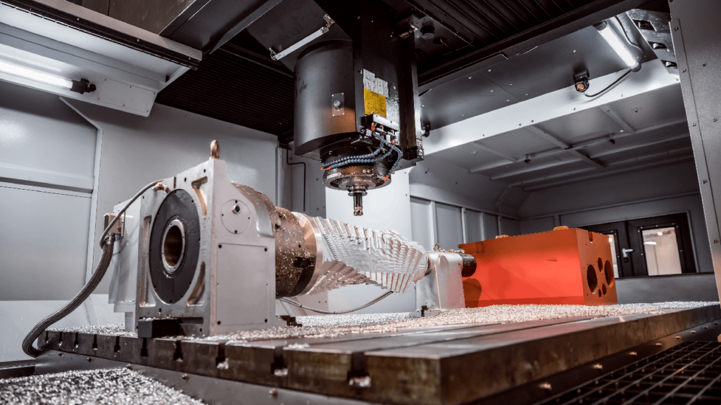
6. CNC Milling Machine

Also known as computer numerical control milling machines, CNC mills are computer-controlled and work with minimal human interaction. Cutting tools are programmed to remove material from flat or contoured surfaces, and cutting materials is typically faster than with manual machines. As a result, CNC milling machines are excellent for production work. Still, because they can machine complex shapes, they are also ideal for custom-designed parts requiring precision, detail, and a better surface finish.

As with any type of machine used for milling, a CNC milling machine relies on rotary cutters moving along multiple axes to complete the milling process. Various types of CNC machines can operate on several axes (sometimes five or more) to produce the kind of complex parts you would find in the aerospace industry.

CNC milling machines are vertical and horizontal machining centers with features including automatic tool changers, tool magazines, enclosed worktables, and coolant systems, all designed for high-quality machining.

Excellent CNC Bridgeport-type vertical knee mills are under $15,000, while large multiple-axis machine tools could cost your company $500,000!

7. Tracer Controlled Milling Machine

Any metal pattern shop producing cast iron patterns for automated foundries in the 1970s had several tracer mills on their shop floor. These machines used a stylus to follow a pattern (usually made of wood and built by expert wood patternmakers) while multiple heads with ball end mills machined cast iron blocks to reproduce patterns, cams, and other contoured surfaces in cast iron or some other metal.

Although tracer-controlled milling machines were standard equipment several decades ago, high-speed 3-axis CNC mills have long replaced the wooden patterns and the talented wood patternmakers who created them. Today, a CNC programmer using sophisticated manufacturing software takes the place of the patternmaker and avoids the pattern altogether.

Since the tracers have lost much of their demand, you can buy them for a few hundred dollars.

8. Column Milling Machines

The column milling machine, or column and knee type, is a blanket term to cover a few of the most common machines, including vertical and horizontal milling machines. So named because the vertical column is attached to the base, and the knee is mounted to guideways allowing it to move vertically.

The column is the primary supporting frame of the knee, worktable, and overarm while housing the driving mechanisms for the spindle and table feed. Column milling machines were typically used to machine car parts, but they work well for operations in various industries.

Since column milling machines cover an extensive range of machines, their costs will vary from a few thousand dollars to hundreds of thousands.

9. Duplex Milling Machine

Duplex milling machines are a combination of two machines placed opposite one another. The two machines work separately or as a single unit when the workpiece is machined with two spindles simultaneously. Duplex spindles can move either horizontally or in vertical directions. And they can be either CNC machine tools or manual machines.

10. Rotary Table Milling Machine

A rotary table is an attachment fastened to a milling machine rather than a separate machine. Typically clamped to a vertical milling machine, it enables precise positioning or allows for cutting round shapes. The rotary table can be fastened either horizontally (flat) on the table or vertically, depending on the shape of the finished part. It can also be operated manually or by CNC control.

Most rotary table attachments start at a few hundred dollars up to about $1,500.

Get the Best of Both Worlds in Your Next Milling Machine

CNC Supra Milling Machine
Supra CNC Milling Machine

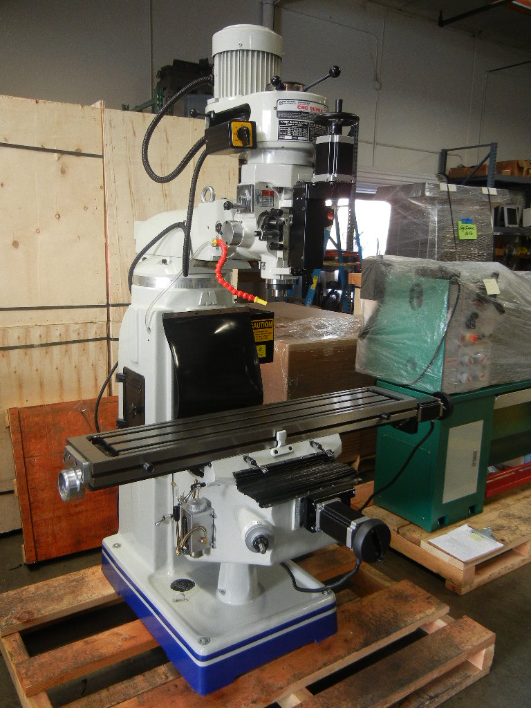
The CNC Supra Vertical Knee Mill is a versatile machine tool from CNC Masters offering computer numerical control and manual-driven operations in one product. This innovative machine enables the machining of complex parts through CNC technology and also provides the option of manually machining simple parts by turning the handwheels.

However, the Supraā€™s versatility doesnā€™t stop there. Itā€™s a machine at home on the shop floor of the largest corporation or in the home workshop of a one-person operation or hobbyist. For smaller companies, start machining your parts at a fraction of the cost of outsourcing them. Larger companies get the benefits of a CNC machine and also one that machines simple parts quickly and effortlessly.

Please email us directly at sales@cncmasters.com, call us at 626-962-9300, or visit our contact page. We look forward to hearing from you!

About Peter Jacobs

Peter Jacobs is the Senior Director of Marketing at CNC Masters, a leading supplier of CNC mills, milling machines, and CNC lathes. He is actively involved in manufacturing processes and regularly contributes his insights for various blogs in CNC machining, 3D printing, rapid tooling, injection molding, metal casting, and manufacturing in general. You can connect with him on his LinkedIn.

Have Questions? Need a Quote?

Looking for more information about our CNC machines and services? Contact us today.

Contact

Slide 1

29. Create a Peck Drilling Program in Circular or Rectangular Patterns
Using the Circular or Rectangular Drilling Wizards, you can program the machine to drill an un-limited series of holes along the X and Y planes. Program it to drill straight through to your total depth, use a high-speed pecking cycle, or deep hole pecking cycle. You can program the cut-in depth and return point for a controlled peck drill application to maximize chip clearance.

Slide 1

20. Change up to 30 tools with compensation, and store your tool offsets for other programs
The MX supports…

Slide 1

21. Use the optional ATC rack up to 8 tools for milling, drilling, and rigid tapping applications
The CNC Masters Automatic Tool Changer Rack and Tools (US Patent 9,827,640B2) can be added to any CNC Masters Milling Machine built with the rigid tapping encoder option. The tutorial will guide you through the set-up procedure using the ATC tools.

Slide 1

22. Use the optional Rigid Tapping Wizard without the need for tapping head attachments
When you order your CNC Masters machine, have it built with the optional rigid tapping encoder. You can take any drill cycle program and replace the top line with a tapping code created by the wizard to tap your series of holes up to 1/2ā€ in diameter.

Slide 1

23. Use the optional Digital Probe to scan the profile and/or pockets of your fun/hobby type designs to write your tool path program and machine out a duplicate of your original design To ā€œsurfaceā€ scan an object, you can program the probe along the X or Y plane. The stylus will travel over the part starting on the left side front corner of the object and work its way to the end of the part on the right side. Depending on how the stylus moves, it will record linear and interpolated movements along the X, Y, and Z planes directly on the MX Editor.
To ā€œpocketā€ scan an object containing a closed pocket such as circles or squares, the scan will start from the top front, work its way inside of the pocket, and scan the entire perimeter of the pocket.
Under the Setup of the MX software you will find the Probe Tab which will allow you to calibrate and program your probe. Your ā€œProbe Stepā€, ā€œFeedā€, and ā€œData Filterā€ can also be changed on the fly while the probe is in the middle of scanning your object.

Slide 1

24. Use work offsets G54-G59 for nesting applications
The work offsets offer you a way to program up to six different machining locations. Itā€™s like having multiple 0.0 locations for different parts. This is very useful especially when using sub-routines/nesting applications.

Slide 1

25. Create a Rectangular Pocket / Slot with our selection of Wizards to help you build a tool path program
The Cycle Wizards for the mill or lathe makes it easy to create a simple tool path without needing to use a CAD and CAM software.
On this Wizard, the Rectangular Pocket / Slots, can be used to form a deep rectangular pocket into your material or machine a slot duplicating as many passes needed to its total depth.

Slide 1

26. Create a Circular Pocket Wizard
Input the total diameter, the step down, and total depth and the code will be generated.

Slide 1

27. Do Thread Milling using a single point cutter Wizard

Slide 1

28. Cut a gear out using the Cut Gear Wizard with the optional Fourth Axis

Slide 1

19. Disable the axis motors to manually hand crank each axis into place
Easily de-energize the axis motors by clicking [Disable Motors] to crank each axis by hand, and then press [Reset Control] to re-energize the axis motors.

Slide 1

30. The MX interface can easily be interchanged from Mill Mode to Lathe Mode
Use this interface for your CNC Masters Lathe. It contains all the same user-friendly features and functions that comes in Mill Mode. Simply go to the Setup page and change the interface.

Slide 1

31. Use Tool Change Compensation or the optional Auto Tool Changer Turret if your application requires more than one tool in a single program
You can offset the length and angle of each tool and record it under Tools in your Setup. The program will automatically pause the latheā€™s movement and spindle allowing you to change out your tool, or allowing the optional ATC Turret to quickly turn to its next tool and continue machining.
On the MX interface, you also have four Tool Position buttons. Select your desired T position, and the auto tool post will quickly turn and lock itself to that position.

Slide 1

32. Use the Lathe Wizard Threading Cycle to help you program your latheā€™s internal or external threads in inches or metric

Slide 1

33. Use the Lathe Wizard Turning / Boring Cycle to help you program simple turning and boring cycles without having to go through a CAM or writing a long program with multiple passes

Slide 1

34. Use the Lathe Wizard Peck Drilling Cycle to help you program your drill applications or for face grooving

Slide 1

35. Facing / Grooving / Part Off Cycle Wizards ā€“ with Constant Surface Speed
These cycles can be used with Constant Surface Speed allowing the spindle speed to increase automatically as the diameter of the part decreases giving your application a consistent workpiece finish. With CSS built into the wizard, there is no need to break down the cycle into multiple paths and multiple spindle speed changes.

Slide 1

36. This is our list of supported G and M codes which can be found under Tools > G Code/ M Code List in the MX
If you plan to use a third-party CAM software to generate your tool path program, use a generic FANUC post processor and edit it to match our list of codes. As an option, we also sell Visual mill/turn CAM software which comes with a guaranteed post processor for our machines to easily generate your tool path programs based on your CAD drawings.

Slide 1

37. Our pledge to you…

Slide 1

10. Run each tool path independently to study its movement
1. Run the machine on Trace mode. You can run each tool path independently, one line at a time to study the tool path movement on the machine to verify the position of the application and if any fixture/vise is in the way of the cutterā€™s path.

2. You can also verify your program by clicking on the Trace and Draw buttons together. This will allow you to view each tool path independently one line at a time in the Draw Window.

Slide 1

2. Clutter Free Interface
The MX is engineered for the CNC MASTERS machine so you do not have to fiddle with a detailed complicated configuration that can be overwhelming. Just load in the MX and start machining!2. Clutter Free Interface
The MX is engineered for the CNC MASTERS machine so you do not have to fiddle with a detailed complicated configuration that can be overwhelming. Just load in the MX and start machining!

Slide 1

3. Features Tour and Tutorials Included
The Features Tour will give you a quick run-down on all the features the MX can do for you. The Tutorials are easy to follow even for the first time CNC machinist.
Feel free to download the MX on any of your computers. We recommend downloading the MX along with your CAD and CAM software there at the comfort of your office computer to generate your tool path programs. You donā€™t need to be hooked up to the machine either to test your program in simulation mode.

Slide 1

4. Navigate and Edit Your Program through the MX interface with Ease
With a few clicks of the mouse or using touch screen technology, you can easily navigate through the MX interface importing saved programs into the Editor from the File drop down menu. Using standard windows features to edit your program you can then lock the Editor Screen to avoid accidental editing, and if you need to insert a line in the middle of a program, just click on [ReNum] to re-number your tool path list.
You can create a program or import CAM generated G-code tool paths into the Editor
The X Y and Z W arrow jog buttons are displayed from the point of view of the cutter to avoid confusion when the table and saddle are moving. You can also adjust your spindle speed and coolant control while jogging each axis.

Slide 1

5. Feed Hold ā€“ Pause in the Middle of your Program
Feed Hold lets you pause in the middle of a program. From there you can step through your program one line at time while opting to shut the spindle off and then resume your program.
You can also write PAUSE in the middle of your program and jog each axis independently while your program is in pause mode.

Slide 1

6. Hot Keys
Hot Keys is an alternative method to easily control your machine using your hard or touch screen keyboard. One can press P to pause a program, press S to turn Spindle On, G to run a program, Space Bar to Stop, J to record your individual movements one line at a time to create a program in teach mode.

Slide 1

7. Pick Menu ā€“ for conversational mode programming
Write FANUC style G-codes directly into the Editor or select commands off the [Pick] menu and write your tool path program in conversational mode such as what is written in the Editor box. You can even mix between conversation commands and G-codes in the same program.

Slide 1

8. Pick Menu List of Options
Use commands such as MOVE, SPINDLE ON/OFF, COOLANT ON/OFF, PAUSE, DELAY, GO HOMEā€¦. to write your tool path programs in conversational mode.

Slide 1

9. Draw the Tool Path to verify it before pressing Go
Hit Draw to view your tool path program drawing, check out its run time, or even simulate the tool path in 3D mode. This can be helpful to quickly verify your program before running it. You can also slow down or speed up the drawing or simulation process.
You can also hit Go within the Draw Window itself to verify the cutterā€™s position on the machine. The current tool path will be highlighted and simultaneously draw out the next path so you can verify what the cutter will be doing next on the program.

Slide 1

MX Software ā€“ Easy to Use, Easy to Learn ā€“ Included with your machine purchase
The MX software is designed to work seamlessly with your CNC Masters machine. It is made to work with Windows PC ā€“ desktop, laptop, or an all in one ā€“ on standard USB. Use it on Windows 8 or 10 64-bit operating systems.
No internal conversion printer/serial port to USB software or additional conversion hardware is used with the MX.

Slide 1

11. Counters display in Inches or Millimeters ā€“ Continuous Feed
1. When running a program, the counters will display a ā€œreal-timeā€ readout while the machine is in CNC operation without counting ahead of the movement.
2. The current tool path is highlighted while the machine is in operation without causing slight interruptions/pauses as the software feeds the tool path to the machine. The MX internally interprets a program ten lines ahead to allow for ā€œcontinuous machiningā€ avoiding slight interruptions as the machine waits for its next tool path command.
3. ā€œRun Timeā€ tells you how long it takes to run your tool path program.

Slide 1

12. Use the ā€œGo From Lineā€ command to start in the middle of your program
If you ever need to begin your program from somewhere in the middle of it, use [Go From Line] which you can find under Tools. The Help guide will walk you through how to position the cutter without losing its position on the machine.

Slide 1

13. Exact Motion Distance without over-stepping on an axis while jogging
Use ā€œRelative ONā€ to enter a specific coordinate to jog any of your axes to an exact location without having to write a program. Itā€™s like using ā€œpower feedā€ but easier. You can jog an exact distance on any of the axes without needing to keep the key pressed down and mistakenly over-step the movement releasing your finger too slowly off the jog button.
Letā€™s say you need to drill a hole exactly 0.525ā€ using the Z. So you enter 0.525 in the Z box. Next, adjust the JOG FEED RATE slider for the desired feed rate. Then ā€œclick onceā€ on the +Z or -Z button to activate the travel. In this case you click once the -Z button first to drill the hole exactly 0.525ā€. Then click once on the +Z button to drive the axis back up 0.525ā€.

Slide 1

14. Teach Mode ā€“ Jog Input
You can create a tool path program by storing each point-to-point movement by simply jogging an axis one at a time. Click on either of the Jog Input buttons to store each movement on the Editor Screen. You can then add Spindle ON, feed commands, and press GO to run the new program as needed. This is a great feature to help you learn to create a program by the movements you make on the machine without necessarily writing out an entire program first.

Slide 1

15. Override on the fly to adjust the Jog Feed to Rapid or the Spindle Speed during the middle of a program
1. Jog Feed and Rapid with Override: You can adjust feeds using the slider from slow minimum 0.1ā€³ per minute to a rapid of 100ā€³ per minute of travel. You can even micro-step your jog as low as 0.01ā€/min. The [-][+] buttons allow you to fine tune feeds in 5% increments while the program is in motion.
2. Spindle Speed with Override: You can adjust speeds using the slider from a slow minimum RPM to the max RPM according to the machine setup. The [-][+] buttons allow you to fine tune feeds in 5% increments while the program is in motion.

Slide 1

16. Adjust Counters using Pre-Set if you cannot begin the program from 0.00
In a situation where you cannot begin your cutter at itā€™s 0.00 location, you can ā€œPre-Setā€ directly into the counters by typing in your beginning coordinate. You can press Go from here to run your program. You can also ā€œzero allā€ or ā€œzeroā€ your counters independently. With one click of the [Return to 0.0] button, all axes will travel back to its respective 0.0 on the machine.

Slide 1

17. Set and Save your 0.00 position for future runs
Set and save your 0.00 position on the machine. These coordinates will be recorded as the first line of the program in the Editor Screen. Should you desire to return to this program at a later date, you only have to click on the Set Zero Return button. This will command the machine to automatically jog each axis to its saved ā€œsetā€ 0.00 position according to the recorded coordinates at the first line of the program.

Slide 1

18. Create a ā€œHomeā€ position to clear your application and run multiple times
Letā€™s say you need to machine one application times 100 pieces. This usually requires a jig to retain that physical 0.00 position. But in this case, you want the program to end with a clearance of the axes to easily switch out the next piece of stock and start again. With Save Home, you have the ability to save this offset (home) position while still retaining your Set Zero position where the machine will mill your part out. Pressing [Save Home] will record this new position under the Set Zero line in your program.
Pressing [Go Home] will jog your axes back to your ā€œsaved homeā€ position where you originally pressed the Save Home command. You can also input GO_HOME from the Pick Menu as its own tool path in your program. At the completion of your program the axes will end at your Home position. Replace your part, then press [Return to 0.0] button to allow the axes to return to its zero position, and press Go to start your next run.

previous arrow
next arrow