CALL US TODAY

CALL US TODAY

bridgeport mill machine

What is a Bridgeport Mill? 10 Things You Should Know

Every machinist since World War II has experienced a Bridgeport milling machine at some point. Many talks about these versatile knee-type vertical milling machines in the same respectful tone usually reserved for their first muscle car as a teen. The machines were once so popular that machinists began calling all vertical manual milling machines ā€œBridgeport,ā€ even though they were manufactured under another brand name.

So, what about these manual vertical knee mills makes them the most recognizable machine tool in the trade? Here are ten things to know about Bridgeport machines that have set them apart from other manual mills:

1. Why is it Called a Bridgeport?

The name originated in Bridgeport, Connecticut, where Rudolph Bannow designed the first Series I standard mill in 1936. The knee mills went on sale in 1938 and were sold by Bridgeport Machines, Inc. Within a few years, they became the standard for vertical mills, and their popularity continues today.

2. Who Makes Bridgeport Mills Today?

In 2002, the machine tool conglomerate Hardinge, Inc. acquired Bridgeport and began making variants of the Bridgeport mill while continuing to manufacture the Bridgeport Series I machine. Many of the newer models of Bridgeport made by Hardinge areĀ CNC machines, meaning they drive the machine transmission using program codes.

V-Series, GX-Series, and XR-Series are todayā€™s models of the Bridgeport mill. These machines are enclosed and have several advanced features.

3. What are the Main Parts of a Bridgeport Mill?

Column

The main casting on the Bridgeport mill is the column, which provides support and stability for all the other machine components. Weighing in at approximately 800 pounds, the column is the heaviest piece on the Bridgeport.

Knee

The knee is another heavy-duty casting supporting the worktable, and it rides vertically on a dovetail on the machineā€™s column. Depending on the height of the workpiece, Bridgeportā€™s operator can raise or lower the table manually, using the vertical feed crank, allowing knee travel along the Z-axis. Once the knee is in the correct position, the operator can lock it.

Saddle

The saddle supports the worktable and is driven by a screw. A dovetail alignment supports it as it moves along the Y-axis (in and out), either by manually turning a cross-feed crank or using a power feed. It can then be locked in position. The sliding surface of the knee that contacts the saddle is hand-scraped, creating surface pockets that allow lubricants to stay in place longer. The saddle travel on a Series I Bridgeport mill is 12ā€.

Worktable

The table sits on top of the saddle and moves along the X-axis (left to right), either by turning one of the handwheels on each end of the table or engaging the power feed if the machine has one. Like other moving parts on the machine, the table has a locking lever to minimize vibrations. T-slots machined into the tableā€™s surface aid in clamping workpieces or vises for machining. The Series I standard mill has a table size of 9ā€ x 49ā€ and a table travel of 35.5ā€.

Turret

The turret sits atop the column and connects it with the ram. Because the turret rotates by loosening up a series of nuts, the cutting head can access otherwise hard-to-reach areas on the worktable. Some mills have a protractor marking on the turret, allowing precise positioning along the worktable.

Ram

The Bridgeportā€™s ram is locked into the dovetail assembly on top of the turret. A rack and pinion mechanism and a crank allow ram travel of 12ā€ in and out, while a large hole on the back of the ram allows for mounting attachments. And because the ram is on a turret, the operator can swing the attachment 180 degrees and use it above the worktable.

Head

The head houses the spindle and the quill. The original Bridgeport mill has a C Head, but the J Head is standard on most Bridgeport mills. The spindle speed range varies depending on the head and motor attached to the machine. Operators can swivel the head 90 degrees left or right and 45 degrees up or down. The tilt joints have protractors to use as a reference for precisely tilting.

Quill

The quill is a unique feature on a Bridgeport mill, enabling it to act as a drill press by moving the spindle up and down using the quill feed handle. The quill travel is 5ā€ and the quill diameter is 3.375. ForĀ boring operations, operators can raise and lower the quill slowly the quill handwheel to raise and lower the quill slowly or use an optional power quill feed. The drilling capacity in mild steel is 1.25ā€ using manual feed and .75ā€ with power feed.

4. Adding Enhanced Accuracy to a Bridgeport Mill

Digital readouts (DRO) from manufacturers like ACU-RITE and Newall make the manually-operated Bridgeport machines help improve productivity and increase the quality of a machined workpiece. An LCD indicates the axis positions, typically the X-axis and Y-axis, but 3-axis models also show the Z-axis position. DROs often come with new Bridgeport mills, but these units can be retrofitted on an older machine.

5. Applications of a Bridgeport Mill

Bridgeport mills are typically the most versatile machines in a machine shop. The rotating turret, movable ram, Z-axis movement from the knee and quill, and tilting head allow machinists to cut almost anything: milling, facing, drilling, tapping, boring, reaming, and angle cuts are some of the standard applications of a Bridgeport mill.

Even though Bridgeport mills have a relatively small footprint, they have a well-earned reputation for rigidity. Machinists can take deep cuts in tough materials on Bridgeports weighing only 2,000 pounds. The reason? Bridgeport mills are manufactured with a solid cast iron frame with excellent vibration-damping qualities that withstand the vibrations and impact of heavy cuts.

As a result, Bridgeport milling machines machine flat or irregularly shaped surfaces with larger face mills and cut gears or slots using smaller end mills. With a drill chuck or R8 collet in the spindle, itā€™s possible to drill, tap, bore, and ream quickly if the machine has a variable speed head. These machines are so well-made that itā€™s possible to broach keyways without fear of damaging them.

6. What is the Difference Between a Bridgeport Mill and Other Mills?

Every milling machine removes material from a workpiece by rotating a cutting tool and feeding (moving) it into the workpiece. Although there are several types of milling machines, they are usually differentiated as knee-type and bed-type.

Although you can mill, drill, bore, and cut slots with either machine, the vertical knee mill is preferred for its versatility and is the most popular milling machine found in most machine shops today. With a knee-type milling machine, the table is mounted on a knee that moves vertically along the column. The knee supports the table and allows for the up and down movement, which is how the machine adjusts the position of the workpiece. The milling head can also be tilted to machine at various angles.

On the other hand, bed-type milling machines feature a fixed table and movable ram, which is the opposite of the knee mill. Bed mills typically have greater load capacity, with a bed mill carrying approximately twice the load of a knee mill. The bed millā€™s cutting tool is mounted on a vertical or horizontal spindle moving along the bed to remove material from the workpiece. One advantage bed mills have other lighter machines is their stability, allowing them to handle larger workpieces.

One advantage of a bed-type milling machine is that it provides greater stability and accuracy than other milling machines due to its sturdy construction and the fact that the workpiece is securely clamped to the bed. Bed-type milling machines are available in various sizes and configurations, from small benchtop models to large, floor-standing machines.

Hereā€™s a comparison of the two types and the difference between the two:

  • Design: The significant difference between a knee and a bed milling machine is their design. A knee mill has a vertically adjustable knee mounted on a column attached to the bed, and the worktable is mounted on the knee and moves along the Z-axis. In contrast, bed mills have a fixed bed to support the worktable and the cutting tool, and the spindle head moves along the bed to perform the machining.
  • Size and capacity: Bed mills are more potent than knee mills. They are designed to handle larger and heavier workpieces, while knee milling machines are typically suitable for small to medium-sized workpieces.
  • Accuracy and precision: Both types of mills offer excellent accuracy and precision.
  • Versatility: Bridgeport milling machines are more versatile since the adjustable knee enables a greater range of cutting operations. Knee mills are ideal for small- to medium-sized machine shops, home workshops, and general-purpose milling operations.

7. Should I Buy a Bridgeport Mill?

The answer will depend on your specific applications and floor space.

These are the advantages of a Bridgeport knee mill:

  • They have a smaller footprint and fit comfortably in the corner of most shops
  • They are high-speed, productive milling machines that need no programming
  • They are easy to learn and operate
  • Perfect for secondary operations such as drilling, tapping, and simple primary machining operations
  • One more advantage if your Bridgeport has a power drawbar for faster tool changes and coolant for specific metals

Remember that a step pulley design is cheaper and easier to repair but time-consuming if you want to be productive.

8. How Much do Bridgeport Mills Cost?

A new Bridgeport Series I standard package includes an R-8 spindle, chrome ways and gibs, and one-shot lube and sells for $19,600. Add a 12-piece collet set with R-8 spindle taper for $642.

9. Are Bridgeport Mills Still Made?

Yes. However, they are now produced by Hardinge, Inc. and they will now manufacture the Bridgeport mills in the companyā€™s Elmira, New York facility.

10. Who Makes the Best Bridgeport Style Mills?

CNC Masters, an American company, offers its Supra 9 x 49 vertical knee mill as a classic Bridgeport-type milling machine with CNC technology on a 9ā€³ x 49ā€³ table size. Like the original, it features heavy-duty construction and space-saving design and is easy to learn and operate. The big difference is in the CNC control with full three-axis interpolated movement with computer variable spindle control.

supra cnc vertical mill
Supra CNC Vertical Milling Machine

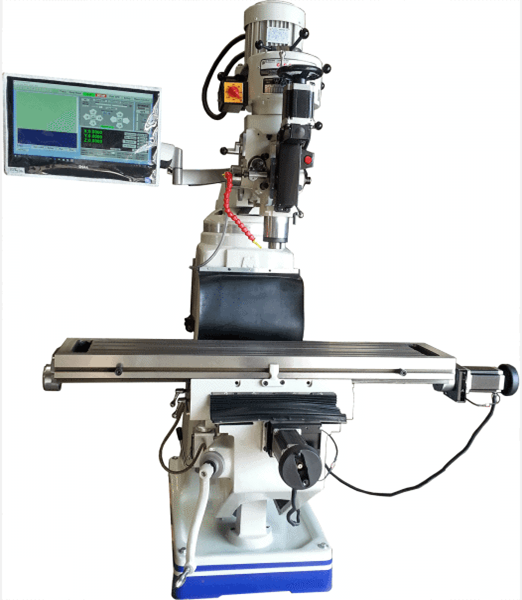
The Supra 9 x 49 mill handles maximum travel of 34ā€ x 11.5ā€ on the X and Y axes, while the Z-axis (spindle axis) is quill driven for accuracy. The best news is that these can switch to manual control and back to CNC control faster than you can say: These must be expensive machine tools! The new Bridgeport manual machine sells for $19,600, while a brand new American-made Supraā€”capable of CNC and manual controlā€”starts at under $13,000!

Why wait? Talk to one of our experts at CNC Masters, and weā€™ll fit you with a CNC mill to increase your production immediately. Please fill out our contact form today!

About Peter Jacobs

Peter Jacobs is the Senior Director of Marketing at CNC Masters, a leading supplier of CNC mills, milling machines, and CNC lathes. He is actively involved in manufacturing processes and regularly contributes his insights for various blogs in CNC machining, 3D printing, rapid tooling, injection molding, metal casting, and manufacturing in general. You can connect with him on his LinkedIn.

Have Questions? Need a Quote?

Looking for more information about our CNC machines and services? Contact us today.

Contact

Slide 1

29. Create a Peck Drilling Program in Circular or Rectangular Patterns
Using the Circular or Rectangular Drilling Wizards, you can program the machine to drill an un-limited series of holes along the X and Y planes. Program it to drill straight through to your total depth, use a high-speed pecking cycle, or deep hole pecking cycle. You can program the cut-in depth and return point for a controlled peck drill application to maximize chip clearance.

Slide 1

20. Change up to 30 tools with compensation, and store your tool offsets for other programs
The MX supports…

Slide 1

21. Use the optional ATC rack up to 8 tools for milling, drilling, and rigid tapping applications
The CNC Masters Automatic Tool Changer Rack and Tools (US Patent 9,827,640B2) can be added to any CNC Masters Milling Machine built with the rigid tapping encoder option. The tutorial will guide you through the set-up procedure using the ATC tools.

Slide 1

22. Use the optional Rigid Tapping Wizard without the need for tapping head attachments
When you order your CNC Masters machine, have it built with the optional rigid tapping encoder. You can take any drill cycle program and replace the top line with a tapping code created by the wizard to tap your series of holes up to 1/2ā€ in diameter.

Slide 1

23. Use the optional Digital Probe to scan the profile and/or pockets of your fun/hobby type designs to write your tool path program and machine out a duplicate of your original design To ā€œsurfaceā€ scan an object, you can program the probe along the X or Y plane. The stylus will travel over the part starting on the left side front corner of the object and work its way to the end of the part on the right side. Depending on how the stylus moves, it will record linear and interpolated movements along the X, Y, and Z planes directly on the MX Editor.
To ā€œpocketā€ scan an object containing a closed pocket such as circles or squares, the scan will start from the top front, work its way inside of the pocket, and scan the entire perimeter of the pocket.
Under the Setup of the MX software you will find the Probe Tab which will allow you to calibrate and program your probe. Your ā€œProbe Stepā€, ā€œFeedā€, and ā€œData Filterā€ can also be changed on the fly while the probe is in the middle of scanning your object.

Slide 1

24. Use work offsets G54-G59 for nesting applications
The work offsets offer you a way to program up to six different machining locations. Itā€™s like having multiple 0.0 locations for different parts. This is very useful especially when using sub-routines/nesting applications.

Slide 1

25. Create a Rectangular Pocket / Slot with our selection of Wizards to help you build a tool path program
The Cycle Wizards for the mill or lathe makes it easy to create a simple tool path without needing to use a CAD and CAM software.
On this Wizard, the Rectangular Pocket / Slots, can be used to form a deep rectangular pocket into your material or machine a slot duplicating as many passes needed to its total depth.

Slide 1

26. Create a Circular Pocket Wizard
Input the total diameter, the step down, and total depth and the code will be generated.

Slide 1

27. Do Thread Milling using a single point cutter Wizard

Slide 1

28. Cut a gear out using the Cut Gear Wizard with the optional Fourth Axis

Slide 1

19. Disable the axis motors to manually hand crank each axis into place
Easily de-energize the axis motors by clicking [Disable Motors] to crank each axis by hand, and then press [Reset Control] to re-energize the axis motors.

Slide 1

30. The MX interface can easily be interchanged from Mill Mode to Lathe Mode
Use this interface for your CNC Masters Lathe. It contains all the same user-friendly features and functions that comes in Mill Mode. Simply go to the Setup page and change the interface.

Slide 1

31. Use Tool Change Compensation or the optional Auto Tool Changer Turret if your application requires more than one tool in a single program
You can offset the length and angle of each tool and record it under Tools in your Setup. The program will automatically pause the latheā€™s movement and spindle allowing you to change out your tool, or allowing the optional ATC Turret to quickly turn to its next tool and continue machining.
On the MX interface, you also have four Tool Position buttons. Select your desired T position, and the auto tool post will quickly turn and lock itself to that position.

Slide 1

32. Use the Lathe Wizard Threading Cycle to help you program your latheā€™s internal or external threads in inches or metric

Slide 1

33. Use the Lathe Wizard Turning / Boring Cycle to help you program simple turning and boring cycles without having to go through a CAM or writing a long program with multiple passes

Slide 1

34. Use the Lathe Wizard Peck Drilling Cycle to help you program your drill applications or for face grooving

Slide 1

35. Facing / Grooving / Part Off Cycle Wizards ā€“ with Constant Surface Speed
These cycles can be used with Constant Surface Speed allowing the spindle speed to increase automatically as the diameter of the part decreases giving your application a consistent workpiece finish. With CSS built into the wizard, there is no need to break down the cycle into multiple paths and multiple spindle speed changes.

Slide 1

36. This is our list of supported G and M codes which can be found under Tools > G Code/ M Code List in the MX
If you plan to use a third-party CAM software to generate your tool path program, use a generic FANUC post processor and edit it to match our list of codes. As an option, we also sell Visual mill/turn CAM software which comes with a guaranteed post processor for our machines to easily generate your tool path programs based on your CAD drawings.

Slide 1

37. Our pledge to you…

Slide 1

10. Run each tool path independently to study its movement
1. Run the machine on Trace mode. You can run each tool path independently, one line at a time to study the tool path movement on the machine to verify the position of the application and if any fixture/vise is in the way of the cutterā€™s path.

2. You can also verify your program by clicking on the Trace and Draw buttons together. This will allow you to view each tool path independently one line at a time in the Draw Window.

Slide 1

2. Clutter Free Interface
The MX is engineered for the CNC MASTERS machine so you do not have to fiddle with a detailed complicated configuration that can be overwhelming. Just load in the MX and start machining!2. Clutter Free Interface
The MX is engineered for the CNC MASTERS machine so you do not have to fiddle with a detailed complicated configuration that can be overwhelming. Just load in the MX and start machining!

Slide 1

3. Features Tour and Tutorials Included
The Features Tour will give you a quick run-down on all the features the MX can do for you. The Tutorials are easy to follow even for the first time CNC machinist.
Feel free to download the MX on any of your computers. We recommend downloading the MX along with your CAD and CAM software there at the comfort of your office computer to generate your tool path programs. You donā€™t need to be hooked up to the machine either to test your program in simulation mode.

Slide 1

4. Navigate and Edit Your Program through the MX interface with Ease
With a few clicks of the mouse or using touch screen technology, you can easily navigate through the MX interface importing saved programs into the Editor from the File drop down menu. Using standard windows features to edit your program you can then lock the Editor Screen to avoid accidental editing, and if you need to insert a line in the middle of a program, just click on [ReNum] to re-number your tool path list.
You can create a program or import CAM generated G-code tool paths into the Editor
The X Y and Z W arrow jog buttons are displayed from the point of view of the cutter to avoid confusion when the table and saddle are moving. You can also adjust your spindle speed and coolant control while jogging each axis.

Slide 1

5. Feed Hold ā€“ Pause in the Middle of your Program
Feed Hold lets you pause in the middle of a program. From there you can step through your program one line at time while opting to shut the spindle off and then resume your program.
You can also write PAUSE in the middle of your program and jog each axis independently while your program is in pause mode.

Slide 1

6. Hot Keys
Hot Keys is an alternative method to easily control your machine using your hard or touch screen keyboard. One can press P to pause a program, press S to turn Spindle On, G to run a program, Space Bar to Stop, J to record your individual movements one line at a time to create a program in teach mode.

Slide 1

7. Pick Menu ā€“ for conversational mode programming
Write FANUC style G-codes directly into the Editor or select commands off the [Pick] menu and write your tool path program in conversational mode such as what is written in the Editor box. You can even mix between conversation commands and G-codes in the same program.

Slide 1

8. Pick Menu List of Options
Use commands such as MOVE, SPINDLE ON/OFF, COOLANT ON/OFF, PAUSE, DELAY, GO HOMEā€¦. to write your tool path programs in conversational mode.

Slide 1

9. Draw the Tool Path to verify it before pressing Go
Hit Draw to view your tool path program drawing, check out its run time, or even simulate the tool path in 3D mode. This can be helpful to quickly verify your program before running it. You can also slow down or speed up the drawing or simulation process.
You can also hit Go within the Draw Window itself to verify the cutterā€™s position on the machine. The current tool path will be highlighted and simultaneously draw out the next path so you can verify what the cutter will be doing next on the program.

Slide 1

MX Software ā€“ Easy to Use, Easy to Learn ā€“ Included with your machine purchase
The MX software is designed to work seamlessly with your CNC Masters machine. It is made to work with Windows PC ā€“ desktop, laptop, or an all in one ā€“ on standard USB. Use it on Windows 8 or 10 64-bit operating systems.
No internal conversion printer/serial port to USB software or additional conversion hardware is used with the MX.

Slide 1

11. Counters display in Inches or Millimeters ā€“ Continuous Feed
1. When running a program, the counters will display a ā€œreal-timeā€ readout while the machine is in CNC operation without counting ahead of the movement.
2. The current tool path is highlighted while the machine is in operation without causing slight interruptions/pauses as the software feeds the tool path to the machine. The MX internally interprets a program ten lines ahead to allow for ā€œcontinuous machiningā€ avoiding slight interruptions as the machine waits for its next tool path command.
3. ā€œRun Timeā€ tells you how long it takes to run your tool path program.

Slide 1

12. Use the ā€œGo From Lineā€ command to start in the middle of your program
If you ever need to begin your program from somewhere in the middle of it, use [Go From Line] which you can find under Tools. The Help guide will walk you through how to position the cutter without losing its position on the machine.

Slide 1

13. Exact Motion Distance without over-stepping on an axis while jogging
Use ā€œRelative ONā€ to enter a specific coordinate to jog any of your axes to an exact location without having to write a program. Itā€™s like using ā€œpower feedā€ but easier. You can jog an exact distance on any of the axes without needing to keep the key pressed down and mistakenly over-step the movement releasing your finger too slowly off the jog button.
Letā€™s say you need to drill a hole exactly 0.525ā€ using the Z. So you enter 0.525 in the Z box. Next, adjust the JOG FEED RATE slider for the desired feed rate. Then ā€œclick onceā€ on the +Z or -Z button to activate the travel. In this case you click once the -Z button first to drill the hole exactly 0.525ā€. Then click once on the +Z button to drive the axis back up 0.525ā€.

Slide 1

14. Teach Mode ā€“ Jog Input
You can create a tool path program by storing each point-to-point movement by simply jogging an axis one at a time. Click on either of the Jog Input buttons to store each movement on the Editor Screen. You can then add Spindle ON, feed commands, and press GO to run the new program as needed. This is a great feature to help you learn to create a program by the movements you make on the machine without necessarily writing out an entire program first.

Slide 1

15. Override on the fly to adjust the Jog Feed to Rapid or the Spindle Speed during the middle of a program
1. Jog Feed and Rapid with Override: You can adjust feeds using the slider from slow minimum 0.1ā€³ per minute to a rapid of 100ā€³ per minute of travel. You can even micro-step your jog as low as 0.01ā€/min. The [-][+] buttons allow you to fine tune feeds in 5% increments while the program is in motion.
2. Spindle Speed with Override: You can adjust speeds using the slider from a slow minimum RPM to the max RPM according to the machine setup. The [-][+] buttons allow you to fine tune feeds in 5% increments while the program is in motion.

Slide 1

16. Adjust Counters using Pre-Set if you cannot begin the program from 0.00
In a situation where you cannot begin your cutter at itā€™s 0.00 location, you can ā€œPre-Setā€ directly into the counters by typing in your beginning coordinate. You can press Go from here to run your program. You can also ā€œzero allā€ or ā€œzeroā€ your counters independently. With one click of the [Return to 0.0] button, all axes will travel back to its respective 0.0 on the machine.

Slide 1

17. Set and Save your 0.00 position for future runs
Set and save your 0.00 position on the machine. These coordinates will be recorded as the first line of the program in the Editor Screen. Should you desire to return to this program at a later date, you only have to click on the Set Zero Return button. This will command the machine to automatically jog each axis to its saved ā€œsetā€ 0.00 position according to the recorded coordinates at the first line of the program.

Slide 1

18. Create a ā€œHomeā€ position to clear your application and run multiple times
Letā€™s say you need to machine one application times 100 pieces. This usually requires a jig to retain that physical 0.00 position. But in this case, you want the program to end with a clearance of the axes to easily switch out the next piece of stock and start again. With Save Home, you have the ability to save this offset (home) position while still retaining your Set Zero position where the machine will mill your part out. Pressing [Save Home] will record this new position under the Set Zero line in your program.
Pressing [Go Home] will jog your axes back to your ā€œsaved homeā€ position where you originally pressed the Save Home command. You can also input GO_HOME from the Pick Menu as its own tool path in your program. At the completion of your program the axes will end at your Home position. Replace your part, then press [Return to 0.0] button to allow the axes to return to its zero position, and press Go to start your next run.

previous arrow
next arrow