CALL US TODAY

CALL US TODAY

filling holes in wood putty

9 Ways to Fill Large Holes in Wood

When working with old wood, it’s often necessary to repair damages such as large holes resulting from rot or poor craftsmanship. Whether you’re diving into a detailed tutorial on advanced woodworking or simply tackling the neverending home improvement list, understanding wood filling is essential. Here are nine commonly used methods to help any DIY-er fill voids and large holes in various types of wood.

Wood Putty

Understanding the wood grain and types of wood you’re working with can influence your choice of wood filling methods. Wood putty is a compound designed for repairing holes in wood. It’s available both pre-made and as a powder that you mix with water. Its color closely resembles wood, making it ideal for blending in holes when the wood grain remains visible, like on wooden furniture.

Although there’s a tutorial on creating your own wood putty using drywall compound and fine sanding dust, many opt for off-the-shelf wood filler putty. While wood putty isn’t the only option for wood filling, it’s among the most popular for filling voids, especially small ones like screw holes in visible locations.

How to Use Wood Putty:

  1. Clean the hole of debris. For deep holes, deepen them slightly using a chisel to ensure the putty fills them entirely.
  2. Follow the package instructions to mix the wood putty. If it’s in powder form, add water until achieving a thick paste consistency.
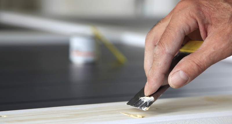
  3. Use a putty knife to fill the hole, applying light pressure in a back-and-forth motion.
  4. Smooth the putty’s surface with the knife, removing any excess.
  5. Allow the putty to dry, typically around 24 hours.
  6. Sand the dried putty with fine-grit sandpaper or an electric sander until smooth. Finish with stain or other products as necessary.

Two-Part Epoxy Resin Products

Epoxy is versatile for filling wood holes, with the best method depending on the hole’s size and shape. Epoxy adheres to wood’s pores and fibers similarly to dyes or varnishes. Most hardware stores carry two-part epoxy kits, which include a hardener to mix with the resin, resulting in a durable, waterproof filler.

For small holes, a putty knife or epoxy ball suffices. For larger holes, consider mixing in sawdust or wood shavings to form a paste. Once the epoxy dries, sand it flush with the wood’s surface. Then, paint or varnish as needed.

Epoxy can also be mixed with sawdust for larger or deeper holes. While epoxy requires some skill, it’s perfect for extensive damage or severely rotted wood.

Shellac Sticks (Burn-In Sticks)

Shellac sticks, also known as burn-in sticks, are solid sticks of colored shellac that can be used to fill small imperfections in wood, including holes, dents, and scratches. They come in various colors to match different types of wood and their respective wood grain.

How to Use Shellac Sticks:

  1. Clean the hole to ensure it’s free of debris and dust.
  2. Heat a burn-in knife (or a regular knife if you don’t have one) using a propane torch or alcohol lamp.
  3. Touch the heated knife to the shellac stick to melt a small amount.
  4. Drip the melted shellac into the hole, slightly overfilling it.
  5. Allow the shellac to cool and harden.
  6. Use a scraper or razor blade to carefully remove the excess, making it flush with the wood surface.
  7. Buff the area with fine steel wool or sandpaper to blend it in.
  8. Finish with a coat of wax or polish to enhance the shine and match the surrounding area.

Wood Glue with Toothpicks

For those who prefer a quick tutorial on using common household items for wood filling, wood glue combined with toothpicks can be an effective solution.

How to use Wood Glue and Toothpicks:

  1. Clean the hole, removing debris or loose wood.
  2. Drip wood glue into the hole until nearly full.
  3. Insert toothpicks until the hole is filled.
  4. Allow the glue to dry, ranging from an hour to 24 hours.
  5. Sand the dried area until it’s flush with the surrounding wood.

Wax Candle

In a pinch, a candle can be substituted as a wood filler. This method is especially useful when trying to match the wood grain of antique pieces.

  1. Trim the candle wick to about 1/4 inch for precision.
  2. Melt the candle’s end slightly.
  3. Drip the wax into the hole, allowing each layer to cool before adding more.
  4. Buff and sand the surface, then stain as desired.

Wood Plugs + Wood Dowels

For a tutorial on advanced wood-filling techniques, using wood plugs or dowels can be a great start. These small pieces of wood are designed to fill holes in other wood pieces, making them ideal for various types of wood.

To use a wood plug:

  1. Determine the hole’s size to select the appropriate plug.
  2. Cut a square or rectangle around the hole using a chisel or knife.
  3. Ensure the plug’s depth is slightly less than the hole’s. Adjust as necessary.
  4. Hammer the plug into the hole. If using a screw, drill a hole in the plug’s center.
  5. Optionally, apply wood glue before inserting the plug.
  6. Finish your project, painting or staining over the plugs.

Sawdust/Glue

For DIY-ers looking for a simple solution to make homemade wood fillers, combining sawdust and wood glue can be a simple and effective method.

  1. Collect fine sawdust from the wood you’re working on. You can get this from sanding the wood or from a saw.
  2. Mix the sawdust with a clear or wood-colored carpenter’s glue in a small container until you achieve a thick, putty-like consistency
  3. Press the mixture into the hole using a putty knife or your finger.
  4. Overfill the hole slightly to account for shrinkage as the filler dries.
  5. Allow the mixture to dry thoroughly. This can take several hours to a day, depending on the size of the hole and the amount of filler used.
  6. Sand the dried filler flush with the wood surface.
  7. Finish with paint, stain, or sealant as desired.

Bondo Polyester Resin Wood Filler

Polyester resin is a type of thermosetting plastic that can be used as a wood filler. It’s often used in marine applications because of its water-resistant properties. When combined with a hardener, it forms a solid, durable fill that can be sanded, painted, or stained and is considered one of the best wood fillers on the market.

How to Use Wood Filler:

  1. Preparation: Clean the hole or damaged area to ensure it’s free from dust, debris, and loose wood particles.
  2. Mixing: In a disposable container, mix the polyester resin with the hardener according to the manufacturer’s instructions. It’s essential to get the proportions right for the resin to cure correctly.
  3. Filling: Using a putty knife or spatula, apply the mixed resin into the hole. Ensure you press the mixture into the hole to avoid any air pockets. Overfill slightly to account for any shrinkage upon drying.
  4. Drying: Allow the resin to cure as per the manufacturer’s recommended time. This can vary but usually takes several hours.
  5. Finishing: Once the resin has fully cured, sand the area until it’s flush with the surrounding wood. You can then paint, stain, or varnish over the filled area to match the rest of the wood.

Caulk

Caulk, especially paintable acrylic or latex caulk, can be used to fill small to medium-sized holes in wood, especially in trim or areas that won’t be subjected to heavy wear.

How to Use Caulk to Fill Wood Holes:

  1. Preparation: Clean the hole or damaged area to ensure it’s free from dust, debris, and loose wood particles.
  2. Application: Cut the tip of the caulk tube at an angle. Using a caulk gun, squeeze the caulk into the hole. Make sure to press the caulk into the hole to avoid air pockets. Overfill slightly as caulk can shrink as it dries.
  3. Smoothing: Wet your finger or a caulk smoothing tool and smooth out the caulk to make it flush with the wood surface.
  4. Drying: Allow the caulk to dry thoroughly. This can vary depending on the type and brand of caulk but usually takes several hours to a day.
  5. Finishing: Once dried, the caulk can be sanded lightly if needed. If the caulk is paintable, you can paint over it to match the rest of the wood.

Caulk is flexible, making it a good choice for areas that might experience some movement or temperature fluctuations. We recommend a water-based paintable acrylic or latex caulk.

Additional Tips on How to Fill Holes In Wood

  • Work on a flat surface for even application.
  • If possible, work in a climate-controlled space to ensure proper drying.
  • Allow ample drying time, especially for larger holes.
  • Sometimes, wood is too rotted to repair. Consider replacing it.
  • Properly prepare your workspace, ensuring cleanliness and having all necessary materials on hand.
  • For larger holes, ensure you have enough filler material. Two-part epoxy kits are ideal.
  • For smaller holes, wood glue, paste, or putty is sufficient. Use wood plugs for precision repairs on delicate items.
  • After repairs, additional paint or stain coats may be necessary for a seamless finish.
  • Always let the filler dry completely before painting or using the wood.

No matter which method you choose to use, make sure to let the material dry completely before you start painting or using the wood again. Otherwise, the paint or finish may not adhere properly.

About Peter Jacobs

Peter Jacobs is the Senior Director of Marketing at CNC Masters, a leading supplier of CNC mills, milling machines, and CNC lathes. He is actively involved in manufacturing processes and regularly contributes his insights for various blogs in CNC machining, 3D printing, rapid tooling, injection molding, metal casting, and manufacturing in general. You can connect with him on his LinkedIn.

Have Questions? Need a Quote?

Looking for more information about our CNC machines and services? Contact us today.

Contact

Slide 1

29. Create a Peck Drilling Program in Circular or Rectangular Patterns
Using the Circular or Rectangular Drilling Wizards, you can program the machine to drill an un-limited series of holes along the X and Y planes. Program it to drill straight through to your total depth, use a high-speed pecking cycle, or deep hole pecking cycle. You can program the cut-in depth and return point for a controlled peck drill application to maximize chip clearance.

Slide 1

20. Change up to 30 tools with compensation, and store your tool offsets for other programs
The MX supports…

Slide 1

21. Use the optional ATC rack up to 8 tools for milling, drilling, and rigid tapping applications
The CNC Masters Automatic Tool Changer Rack and Tools (US Patent 9,827,640B2) can be added to any CNC Masters Milling Machine built with the rigid tapping encoder option. The tutorial will guide you through the set-up procedure using the ATC tools.

Slide 1

22. Use the optional Rigid Tapping Wizard without the need for tapping head attachments
When you order your CNC Masters machine, have it built with the optional rigid tapping encoder. You can take any drill cycle program and replace the top line with a tapping code created by the wizard to tap your series of holes up to 1/2ā€ in diameter.

Slide 1

23. Use the optional Digital Probe to scan the profile and/or pockets of your fun/hobby type designs to write your tool path program and machine out a duplicate of your original design To ā€œsurfaceā€ scan an object, you can program the probe along the X or Y plane. The stylus will travel over the part starting on the left side front corner of the object and work its way to the end of the part on the right side. Depending on how the stylus moves, it will record linear and interpolated movements along the X, Y, and Z planes directly on the MX Editor.
To ā€œpocketā€ scan an object containing a closed pocket such as circles or squares, the scan will start from the top front, work its way inside of the pocket, and scan the entire perimeter of the pocket.
Under the Setup of the MX software you will find the Probe Tab which will allow you to calibrate and program your probe. Your ā€œProbe Stepā€, ā€œFeedā€, and ā€œData Filterā€ can also be changed on the fly while the probe is in the middle of scanning your object.

Slide 1

24. Use work offsets G54-G59 for nesting applications
The work offsets offer you a way to program up to six different machining locations. Itā€™s like having multiple 0.0 locations for different parts. This is very useful especially when using sub-routines/nesting applications.

Slide 1

25. Create a Rectangular Pocket / Slot with our selection of Wizards to help you build a tool path program
The Cycle Wizards for the mill or lathe makes it easy to create a simple tool path without needing to use a CAD and CAM software.
On this Wizard, the Rectangular Pocket / Slots, can be used to form a deep rectangular pocket into your material or machine a slot duplicating as many passes needed to its total depth.

Slide 1

26. Create a Circular Pocket Wizard
Input the total diameter, the step down, and total depth and the code will be generated.

Slide 1

27. Do Thread Milling using a single point cutter Wizard

Slide 1

28. Cut a gear out using the Cut Gear Wizard with the optional Fourth Axis

Slide 1

19. Disable the axis motors to manually hand crank each axis into place
Easily de-energize the axis motors by clicking [Disable Motors] to crank each axis by hand, and then press [Reset Control] to re-energize the axis motors.

Slide 1

30. The MX interface can easily be interchanged from Mill Mode to Lathe Mode
Use this interface for your CNC Masters Lathe. It contains all the same user-friendly features and functions that comes in Mill Mode. Simply go to the Setup page and change the interface.

Slide 1

31. Use Tool Change Compensation or the optional Auto Tool Changer Turret if your application requires more than one tool in a single program
You can offset the length and angle of each tool and record it under Tools in your Setup. The program will automatically pause the latheā€™s movement and spindle allowing you to change out your tool, or allowing the optional ATC Turret to quickly turn to its next tool and continue machining.
On the MX interface, you also have four Tool Position buttons. Select your desired T position, and the auto tool post will quickly turn and lock itself to that position.

Slide 1

32. Use the Lathe Wizard Threading Cycle to help you program your latheā€™s internal or external threads in inches or metric

Slide 1

33. Use the Lathe Wizard Turning / Boring Cycle to help you program simple turning and boring cycles without having to go through a CAM or writing a long program with multiple passes

Slide 1

34. Use the Lathe Wizard Peck Drilling Cycle to help you program your drill applications or for face grooving

Slide 1

35. Facing / Grooving / Part Off Cycle Wizards ā€“ with Constant Surface Speed
These cycles can be used with Constant Surface Speed allowing the spindle speed to increase automatically as the diameter of the part decreases giving your application a consistent workpiece finish. With CSS built into the wizard, there is no need to break down the cycle into multiple paths and multiple spindle speed changes.

Slide 1

36. This is our list of supported G and M codes which can be found under Tools > G Code/ M Code List in the MX
If you plan to use a third-party CAM software to generate your tool path program, use a generic FANUC post processor and edit it to match our list of codes. As an option, we also sell Visual mill/turn CAM software which comes with a guaranteed post processor for our machines to easily generate your tool path programs based on your CAD drawings.

Slide 1

37. Our pledge to you…

Slide 1

10. Run each tool path independently to study its movement
1. Run the machine on Trace mode. You can run each tool path independently, one line at a time to study the tool path movement on the machine to verify the position of the application and if any fixture/vise is in the way of the cutterā€™s path.

2. You can also verify your program by clicking on the Trace and Draw buttons together. This will allow you to view each tool path independently one line at a time in the Draw Window.

Slide 1

2. Clutter Free Interface
The MX is engineered for the CNC MASTERS machine so you do not have to fiddle with a detailed complicated configuration that can be overwhelming. Just load in the MX and start machining!2. Clutter Free Interface
The MX is engineered for the CNC MASTERS machine so you do not have to fiddle with a detailed complicated configuration that can be overwhelming. Just load in the MX and start machining!

Slide 1

3. Features Tour and Tutorials Included
The Features Tour will give you a quick run-down on all the features the MX can do for you. The Tutorials are easy to follow even for the first time CNC machinist.
Feel free to download the MX on any of your computers. We recommend downloading the MX along with your CAD and CAM software there at the comfort of your office computer to generate your tool path programs. You donā€™t need to be hooked up to the machine either to test your program in simulation mode.

Slide 1

4. Navigate and Edit Your Program through the MX interface with Ease
With a few clicks of the mouse or using touch screen technology, you can easily navigate through the MX interface importing saved programs into the Editor from the File drop down menu. Using standard windows features to edit your program you can then lock the Editor Screen to avoid accidental editing, and if you need to insert a line in the middle of a program, just click on [ReNum] to re-number your tool path list.
You can create a program or import CAM generated G-code tool paths into the Editor
The X Y and Z W arrow jog buttons are displayed from the point of view of the cutter to avoid confusion when the table and saddle are moving. You can also adjust your spindle speed and coolant control while jogging each axis.

Slide 1

5. Feed Hold ā€“ Pause in the Middle of your Program
Feed Hold lets you pause in the middle of a program. From there you can step through your program one line at time while opting to shut the spindle off and then resume your program.
You can also write PAUSE in the middle of your program and jog each axis independently while your program is in pause mode.

Slide 1

6. Hot Keys
Hot Keys is an alternative method to easily control your machine using your hard or touch screen keyboard. One can press P to pause a program, press S to turn Spindle On, G to run a program, Space Bar to Stop, J to record your individual movements one line at a time to create a program in teach mode.

Slide 1

7. Pick Menu ā€“ for conversational mode programming
Write FANUC style G-codes directly into the Editor or select commands off the [Pick] menu and write your tool path program in conversational mode such as what is written in the Editor box. You can even mix between conversation commands and G-codes in the same program.

Slide 1

8. Pick Menu List of Options
Use commands such as MOVE, SPINDLE ON/OFF, COOLANT ON/OFF, PAUSE, DELAY, GO HOMEā€¦. to write your tool path programs in conversational mode.

Slide 1

9. Draw the Tool Path to verify it before pressing Go
Hit Draw to view your tool path program drawing, check out its run time, or even simulate the tool path in 3D mode. This can be helpful to quickly verify your program before running it. You can also slow down or speed up the drawing or simulation process.
You can also hit Go within the Draw Window itself to verify the cutterā€™s position on the machine. The current tool path will be highlighted and simultaneously draw out the next path so you can verify what the cutter will be doing next on the program.

Slide 1

MX Software ā€“ Easy to Use, Easy to Learn ā€“ Included with your machine purchase
The MX software is designed to work seamlessly with your CNC Masters machine. It is made to work with Windows PC ā€“ desktop, laptop, or an all in one ā€“ on standard USB. Use it on Windows 8 or 10 64-bit operating systems.
No internal conversion printer/serial port to USB software or additional conversion hardware is used with the MX.

Slide 1

11. Counters display in Inches or Millimeters ā€“ Continuous Feed
1. When running a program, the counters will display a ā€œreal-timeā€ readout while the machine is in CNC operation without counting ahead of the movement.
2. The current tool path is highlighted while the machine is in operation without causing slight interruptions/pauses as the software feeds the tool path to the machine. The MX internally interprets a program ten lines ahead to allow for ā€œcontinuous machiningā€ avoiding slight interruptions as the machine waits for its next tool path command.
3. ā€œRun Timeā€ tells you how long it takes to run your tool path program.

Slide 1

12. Use the ā€œGo From Lineā€ command to start in the middle of your program
If you ever need to begin your program from somewhere in the middle of it, use [Go From Line] which you can find under Tools. The Help guide will walk you through how to position the cutter without losing its position on the machine.

Slide 1

13. Exact Motion Distance without over-stepping on an axis while jogging
Use ā€œRelative ONā€ to enter a specific coordinate to jog any of your axes to an exact location without having to write a program. Itā€™s like using ā€œpower feedā€ but easier. You can jog an exact distance on any of the axes without needing to keep the key pressed down and mistakenly over-step the movement releasing your finger too slowly off the jog button.
Letā€™s say you need to drill a hole exactly 0.525ā€ using the Z. So you enter 0.525 in the Z box. Next, adjust the JOG FEED RATE slider for the desired feed rate. Then ā€œclick onceā€ on the +Z or -Z button to activate the travel. In this case you click once the -Z button first to drill the hole exactly 0.525ā€. Then click once on the +Z button to drive the axis back up 0.525ā€.

Slide 1

14. Teach Mode ā€“ Jog Input
You can create a tool path program by storing each point-to-point movement by simply jogging an axis one at a time. Click on either of the Jog Input buttons to store each movement on the Editor Screen. You can then add Spindle ON, feed commands, and press GO to run the new program as needed. This is a great feature to help you learn to create a program by the movements you make on the machine without necessarily writing out an entire program first.

Slide 1

15. Override on the fly to adjust the Jog Feed to Rapid or the Spindle Speed during the middle of a program
1. Jog Feed and Rapid with Override: You can adjust feeds using the slider from slow minimum 0.1ā€³ per minute to a rapid of 100ā€³ per minute of travel. You can even micro-step your jog as low as 0.01ā€/min. The [-][+] buttons allow you to fine tune feeds in 5% increments while the program is in motion.
2. Spindle Speed with Override: You can adjust speeds using the slider from a slow minimum RPM to the max RPM according to the machine setup. The [-][+] buttons allow you to fine tune feeds in 5% increments while the program is in motion.

Slide 1

16. Adjust Counters using Pre-Set if you cannot begin the program from 0.00
In a situation where you cannot begin your cutter at itā€™s 0.00 location, you can ā€œPre-Setā€ directly into the counters by typing in your beginning coordinate. You can press Go from here to run your program. You can also ā€œzero allā€ or ā€œzeroā€ your counters independently. With one click of the [Return to 0.0] button, all axes will travel back to its respective 0.0 on the machine.

Slide 1

17. Set and Save your 0.00 position for future runs
Set and save your 0.00 position on the machine. These coordinates will be recorded as the first line of the program in the Editor Screen. Should you desire to return to this program at a later date, you only have to click on the Set Zero Return button. This will command the machine to automatically jog each axis to its saved ā€œsetā€ 0.00 position according to the recorded coordinates at the first line of the program.

Slide 1

18. Create a ā€œHomeā€ position to clear your application and run multiple times
Letā€™s say you need to machine one application times 100 pieces. This usually requires a jig to retain that physical 0.00 position. But in this case, you want the program to end with a clearance of the axes to easily switch out the next piece of stock and start again. With Save Home, you have the ability to save this offset (home) position while still retaining your Set Zero position where the machine will mill your part out. Pressing [Save Home] will record this new position under the Set Zero line in your program.
Pressing [Go Home] will jog your axes back to your ā€œsaved homeā€ position where you originally pressed the Save Home command. You can also input GO_HOME from the Pick Menu as its own tool path in your program. At the completion of your program the axes will end at your Home position. Replace your part, then press [Return to 0.0] button to allow the axes to return to its zero position, and press Go to start your next run.

previous arrow
next arrow