CALL US TODAY

CALL US TODAY

cnc cutter laser cutter

CNC Cutting vs. Laser Cutting: The Differences Explained

Many smaller machine shops and fabricators, along with hobbyists working from a garage or workshop, are looking to replace or add to their manual machines with computerized equipment. Many of our customers have questions, especially on machine tools that, on the surface, appear to function pretty much the same.

Two such machines are the CNC machine and the laser cutter. Both are high-speed machines capable of the precision cutting of parts with intricate shapes, and they are reliable, fast, and provide excellent repeatability. But the differences between the two methods are not subtle, and they require that you know the specifics of each so that you will make the right choice for your operation.Ā Ā 

Here’s what you should know:

What is CNC cutting?

Computer Numeric Control, better known as CNC, uses dedicated tooling to produce various shapes and sizes of parts. When a designer creates a drawing based on a customer’s specifications, the process begins. Unlike the traditional blueprint made by hand on a drawing board, today’s designer is equipped with software, such as CorelDRAW or AutoCAD, allowing them to complete the drawing on a computer.

Using the computerized drawing, a CNC programmer will translate it to a workpiece with the help of computer-aided manufacturing (CAM) software. The CAM software allows the programmer to create a toolpath and generate the G-code that controls the CNC machine. The computer then sends the program to a CNC machine that can interpret the design.

In the cases of CNC milling machines and CNC routers, the cutting tool moves side-to-side along an “X” axis, in and out along the “Y” axis, and up and down on the “Z” axis. Both a CNC milling machine and a CNC router could move and cut along all three axes simultaneously.

Both types of CNC machines employ cutting tools to remove material. CNC milling requires end mills made of numerous materials, diameters, and cutting lengths, while router bits also come in many different materials and shapes to accommodate various applications. The types of CNC cutting tools are extensive and depend on several factors, including the types of cutting materials, the depth of cut, and the type of cutting you’re doing.

What are the primary benefits of the CNC machine?

So far, we have talked about CNC milling and CNC routing under the blanket term of CNC machines. However, although these two types have much in common, there are a few differences. They both use cutting tools to mill, drill, and cut steel, aluminum, plastic, and wood to create parts or products.

The differences lie in two areas: the types of materials and the movements of the cutting heads. Generally speaking, the companies will use a CNC router to cut wood and other softer materials like acrylic and MDF. Also, the cutting head will move around a stationary cutting area in all three axes.

On the other hand, they tend to choose CNC milling machines for metalworking, and the workpiece moves while the cutting head remains stationary. These machines can make thicker cuts and move more slowly because of their high power and torque. By contrast, the CNC router is a high-speed machine.

Here are just some of the advantages of CNC machines:

  • These CNC machines run on sophisticated software that determines the best way to machine a component with a minimum of waste.
  • Because they do their machining without human intervention, there is little chance for human error, resulting in zero defects and higher accuracy.
  • CNC machines can be set to the highest speeds and feeds to ensure higher productivity and efficiency.
  • CNC machines reduce power consumption, helping to lower overall production costs.
  • Most importantly, CNC machines produce parts without having an operator in harm’s way, reducing the risk of workplace accidents

Who would use a CNC machine?

Because a CNC machine provides a versatile and relatively low-cost cutting process, a diverse assortment of industries and sectors have them on their shop floors for various applications. They can manage practically all metallic materials, along with others as well. The types of parts, components, and products they can produce are virtually limitless.

And because they are available as a desktop CNC milling machine for the smaller shop and hobbyist to the sophisticated multi-axis machine tool for larger corporations, you will find them practically everywhere.

Here are just some of the industries and applications for CNC cutting:

  • Defense industry: CNC cutting is ideal for a military sector needing parts that hold up under extreme conditions. The CNC can also produce replacement parts updated for security or improvement.
  • Oil and gas industry: The CNC machine provides the critical tolerances that a safety-conscious sector requires.
  • Aerospace industry: Aircraft components come in many shapes, sizes, and materials, and they all have one thing in common: they require the high level of precision that a CNC machine can provide.
  • Healthcare: CNC machines provide specific medical components, including implants, electronic enclosures, orthotics, and surgical instruments.
  • Rapid prototyping in all industries: A CNC machine can produce a prototype quickly after a digital design is created.
  • Indirect manufacturing processes: CNC machines can produce molds for injection molding or metal patterns used for sand castings.
  • Jobbing work: Although the CNC machine is perfect for production, many jobbing shops use it for custom work. In many cases, programming, setting up, and machining a few parts is faster (and more accurate) than using a manual machine.
  • Hobbyists and moonlighters: CNC benchtop mills and freestanding knee mills are at home in many garages and home workshops. Whether itā€™s for a hobby or to make extra cash, the CNC mill is an affordable and accessible piece of equipment.

What is laser cutting?

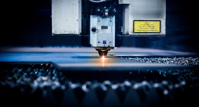
The laser cutter is similar to CNC milling and routing since they all follow a path that is programmed in advance. However, how they accomplish the cutting is as different as night and day. Instead of a cutting tool or router bit, the laser cutter relies on a high-energy light beam to burn through the material. By aiming a high-power laser (Light Amplification by Stimulated Emission of Radiation) through optics, the extreme heat burns the shape into the workpiece.

The laser cutting machine comes in three primary types:

  • The CO2 laser runs electricity through a tube filled with a mixture of carbon dioxide, hydrogen, nitrogen, and helium. While the CO2 laser can cut thin metal sheets, it is typically used in woodworking and as an engraving machine.
  • A fiber laser is a solid-state machine that amplifies its beam using special glass fibers. Known as versatile machines, fiber lasers work with metals, alloys, and non-metals such as wood, plastic, and even glass.
  • The Nd: YAG laser allows for high power cutting using nd:Yag crystals. Unfortunately, these machines have a hefty price tag and a relatively short life expectancy.

What are the main advantages of the laser cutter?

  • One of the most notable advantages of laser cutting is getting detailed cuts. The smallest inside radius you can expect with a cutting tool is around .062″ using a 1/8″ diameter end mill. By contrast, a laser operator can set the laser beam to get a radius of about .005″, providing finer detail.
  • Laser cutting leaves the edges clean and sealed, improving the functionality and appearance of finished parts.
  • Laser cutting maximizes the number of usable parts and produces less waste.
  • CNC laser cutting tools have few moving parts, which reduces maintenance and repair costs.
  • No clamping necessary

Who would choose a CNC laser for their cutting process?

Laser cutting serves various industries, with the shipbuilding, aerospace, and medical sectors leading the way. Steel plates make up most of the materials used in shipbuilding. With the precision that laser cutters afford, the transfer accuracy and hull segmentation required by shipbuilders make the CNC laser a good choice.

Aerospace has many of the same requirements as shipbuilding, and the medical sector needs lasers to manufacture some of their intricate medical devices. Other industries that utilize laser cutting machines include:

  • Automotive for the thousands of small parts that make up the typical vehicle
  • Electronics because laser cutting machines can cut and perforate complex parts and tiny components.Ā 
  • Tool manufacturers use laser engravers to mark and engrave their products and also to manufacture some of their hand tools
  • Fabricators have a constant need for sheet metal components, and the laser cutter can provide a large cutting area for them
  • Musical instruments are often hand-crafted, but many mass manufacturers count on CNC lasers for quality control.
  • Jewelry making is another sector where the precision of laser cutting makes it a good choice.

Be aware that a laser cutter’s complexity, complicated maintenance, and the high cost of ownership may be prohibitive factors for some small businesses and hobbyists. As the above list of users indicates, laser cutting technology is well-suited to large companies.

Also, keep in mind that although some laser cutters can cut material as thick as 3/4″, most of them work better on 1/2″ or less material. And when it comes to wood, a CNC router is a better choice to handle thick materials

Transition to a CNC machine by first talking to the experts

At CNC Masters, we have been providing high-quality CNC tabletop mills, milling machines, and CNC lathes for 20 years. Business owners, machinists, scientists, researchers, teachers, and even hobbyists have discovered our California-based company’s superior quality, affordable prices, and professional service.

Call us at 626-962-9300 or email us at sales@cncmasters.com. Better yet, call us for an appointment and visit our facility in Irwindale, CA.

Have Questions? Need a Quote?

Looking for more information about our CNC machines and services? Contact us today.

Contact

Slide 1

29. Create a Peck Drilling Program in Circular or Rectangular Patterns
Using the Circular or Rectangular Drilling Wizards, you can program the machine to drill an un-limited series of holes along the X and Y planes. Program it to drill straight through to your total depth, use a high-speed pecking cycle, or deep hole pecking cycle. You can program the cut-in depth and return point for a controlled peck drill application to maximize chip clearance.

Slide 1

20. Change up to 30 tools with compensation, and store your tool offsets for other programs
The MX supports…

Slide 1

21. Use the optional ATC rack up to 8 tools for milling, drilling, and rigid tapping applications
The CNC Masters Automatic Tool Changer Rack and Tools (US Patent 9,827,640B2) can be added to any CNC Masters Milling Machine built with the rigid tapping encoder option. The tutorial will guide you through the set-up procedure using the ATC tools.

Slide 1

22. Use the optional Rigid Tapping Wizard without the need for tapping head attachments
When you order your CNC Masters machine, have it built with the optional rigid tapping encoder. You can take any drill cycle program and replace the top line with a tapping code created by the wizard to tap your series of holes up to 1/2ā€ in diameter.

Slide 1

23. Use the optional Digital Probe to scan the profile and/or pockets of your fun/hobby type designs to write your tool path program and machine out a duplicate of your original design To ā€œsurfaceā€ scan an object, you can program the probe along the X or Y plane. The stylus will travel over the part starting on the left side front corner of the object and work its way to the end of the part on the right side. Depending on how the stylus moves, it will record linear and interpolated movements along the X, Y, and Z planes directly on the MX Editor.
To ā€œpocketā€ scan an object containing a closed pocket such as circles or squares, the scan will start from the top front, work its way inside of the pocket, and scan the entire perimeter of the pocket.
Under the Setup of the MX software you will find the Probe Tab which will allow you to calibrate and program your probe. Your ā€œProbe Stepā€, ā€œFeedā€, and ā€œData Filterā€ can also be changed on the fly while the probe is in the middle of scanning your object.

Slide 1

24. Use work offsets G54-G59 for nesting applications
The work offsets offer you a way to program up to six different machining locations. Itā€™s like having multiple 0.0 locations for different parts. This is very useful especially when using sub-routines/nesting applications.

Slide 1

25. Create a Rectangular Pocket / Slot with our selection of Wizards to help you build a tool path program
The Cycle Wizards for the mill or lathe makes it easy to create a simple tool path without needing to use a CAD and CAM software.
On this Wizard, the Rectangular Pocket / Slots, can be used to form a deep rectangular pocket into your material or machine a slot duplicating as many passes needed to its total depth.

Slide 1

26. Create a Circular Pocket Wizard
Input the total diameter, the step down, and total depth and the code will be generated.

Slide 1

27. Do Thread Milling using a single point cutter Wizard

Slide 1

28. Cut a gear out using the Cut Gear Wizard with the optional Fourth Axis

Slide 1

19. Disable the axis motors to manually hand crank each axis into place
Easily de-energize the axis motors by clicking [Disable Motors] to crank each axis by hand, and then press [Reset Control] to re-energize the axis motors.

Slide 1

30. The MX interface can easily be interchanged from Mill Mode to Lathe Mode
Use this interface for your CNC Masters Lathe. It contains all the same user-friendly features and functions that comes in Mill Mode. Simply go to the Setup page and change the interface.

Slide 1

31. Use Tool Change Compensation or the optional Auto Tool Changer Turret if your application requires more than one tool in a single program
You can offset the length and angle of each tool and record it under Tools in your Setup. The program will automatically pause the latheā€™s movement and spindle allowing you to change out your tool, or allowing the optional ATC Turret to quickly turn to its next tool and continue machining.
On the MX interface, you also have four Tool Position buttons. Select your desired T position, and the auto tool post will quickly turn and lock itself to that position.

Slide 1

32. Use the Lathe Wizard Threading Cycle to help you program your latheā€™s internal or external threads in inches or metric

Slide 1

33. Use the Lathe Wizard Turning / Boring Cycle to help you program simple turning and boring cycles without having to go through a CAM or writing a long program with multiple passes

Slide 1

34. Use the Lathe Wizard Peck Drilling Cycle to help you program your drill applications or for face grooving

Slide 1

35. Facing / Grooving / Part Off Cycle Wizards ā€“ with Constant Surface Speed
These cycles can be used with Constant Surface Speed allowing the spindle speed to increase automatically as the diameter of the part decreases giving your application a consistent workpiece finish. With CSS built into the wizard, there is no need to break down the cycle into multiple paths and multiple spindle speed changes.

Slide 1

36. This is our list of supported G and M codes which can be found under Tools > G Code/ M Code List in the MX
If you plan to use a third-party CAM software to generate your tool path program, use a generic FANUC post processor and edit it to match our list of codes. As an option, we also sell Visual mill/turn CAM software which comes with a guaranteed post processor for our machines to easily generate your tool path programs based on your CAD drawings.

Slide 1

37. Our pledge to you…

Slide 1

10. Run each tool path independently to study its movement
1. Run the machine on Trace mode. You can run each tool path independently, one line at a time to study the tool path movement on the machine to verify the position of the application and if any fixture/vise is in the way of the cutterā€™s path.

2. You can also verify your program by clicking on the Trace and Draw buttons together. This will allow you to view each tool path independently one line at a time in the Draw Window.

Slide 1

2. Clutter Free Interface
The MX is engineered for the CNC MASTERS machine so you do not have to fiddle with a detailed complicated configuration that can be overwhelming. Just load in the MX and start machining!2. Clutter Free Interface
The MX is engineered for the CNC MASTERS machine so you do not have to fiddle with a detailed complicated configuration that can be overwhelming. Just load in the MX and start machining!

Slide 1

3. Features Tour and Tutorials Included
The Features Tour will give you a quick run-down on all the features the MX can do for you. The Tutorials are easy to follow even for the first time CNC machinist.
Feel free to download the MX on any of your computers. We recommend downloading the MX along with your CAD and CAM software there at the comfort of your office computer to generate your tool path programs. You donā€™t need to be hooked up to the machine either to test your program in simulation mode.

Slide 1

4. Navigate and Edit Your Program through the MX interface with Ease
With a few clicks of the mouse or using touch screen technology, you can easily navigate through the MX interface importing saved programs into the Editor from the File drop down menu. Using standard windows features to edit your program you can then lock the Editor Screen to avoid accidental editing, and if you need to insert a line in the middle of a program, just click on [ReNum] to re-number your tool path list.
You can create a program or import CAM generated G-code tool paths into the Editor
The X Y and Z W arrow jog buttons are displayed from the point of view of the cutter to avoid confusion when the table and saddle are moving. You can also adjust your spindle speed and coolant control while jogging each axis.

Slide 1

5. Feed Hold ā€“ Pause in the Middle of your Program
Feed Hold lets you pause in the middle of a program. From there you can step through your program one line at time while opting to shut the spindle off and then resume your program.
You can also write PAUSE in the middle of your program and jog each axis independently while your program is in pause mode.

Slide 1

6. Hot Keys
Hot Keys is an alternative method to easily control your machine using your hard or touch screen keyboard. One can press P to pause a program, press S to turn Spindle On, G to run a program, Space Bar to Stop, J to record your individual movements one line at a time to create a program in teach mode.

Slide 1

7. Pick Menu ā€“ for conversational mode programming
Write FANUC style G-codes directly into the Editor or select commands off the [Pick] menu and write your tool path program in conversational mode such as what is written in the Editor box. You can even mix between conversation commands and G-codes in the same program.

Slide 1

8. Pick Menu List of Options
Use commands such as MOVE, SPINDLE ON/OFF, COOLANT ON/OFF, PAUSE, DELAY, GO HOMEā€¦. to write your tool path programs in conversational mode.

Slide 1

9. Draw the Tool Path to verify it before pressing Go
Hit Draw to view your tool path program drawing, check out its run time, or even simulate the tool path in 3D mode. This can be helpful to quickly verify your program before running it. You can also slow down or speed up the drawing or simulation process.
You can also hit Go within the Draw Window itself to verify the cutterā€™s position on the machine. The current tool path will be highlighted and simultaneously draw out the next path so you can verify what the cutter will be doing next on the program.

Slide 1

MX Software ā€“ Easy to Use, Easy to Learn ā€“ Included with your machine purchase
The MX software is designed to work seamlessly with your CNC Masters machine. It is made to work with Windows PC ā€“ desktop, laptop, or an all in one ā€“ on standard USB. Use it on Windows 8 or 10 64-bit operating systems.
No internal conversion printer/serial port to USB software or additional conversion hardware is used with the MX.

Slide 1

11. Counters display in Inches or Millimeters ā€“ Continuous Feed
1. When running a program, the counters will display a ā€œreal-timeā€ readout while the machine is in CNC operation without counting ahead of the movement.
2. The current tool path is highlighted while the machine is in operation without causing slight interruptions/pauses as the software feeds the tool path to the machine. The MX internally interprets a program ten lines ahead to allow for ā€œcontinuous machiningā€ avoiding slight interruptions as the machine waits for its next tool path command.
3. ā€œRun Timeā€ tells you how long it takes to run your tool path program.

Slide 1

12. Use the ā€œGo From Lineā€ command to start in the middle of your program
If you ever need to begin your program from somewhere in the middle of it, use [Go From Line] which you can find under Tools. The Help guide will walk you through how to position the cutter without losing its position on the machine.

Slide 1

13. Exact Motion Distance without over-stepping on an axis while jogging
Use ā€œRelative ONā€ to enter a specific coordinate to jog any of your axes to an exact location without having to write a program. Itā€™s like using ā€œpower feedā€ but easier. You can jog an exact distance on any of the axes without needing to keep the key pressed down and mistakenly over-step the movement releasing your finger too slowly off the jog button.
Letā€™s say you need to drill a hole exactly 0.525ā€ using the Z. So you enter 0.525 in the Z box. Next, adjust the JOG FEED RATE slider for the desired feed rate. Then ā€œclick onceā€ on the +Z or -Z button to activate the travel. In this case you click once the -Z button first to drill the hole exactly 0.525ā€. Then click once on the +Z button to drive the axis back up 0.525ā€.

Slide 1

14. Teach Mode ā€“ Jog Input
You can create a tool path program by storing each point-to-point movement by simply jogging an axis one at a time. Click on either of the Jog Input buttons to store each movement on the Editor Screen. You can then add Spindle ON, feed commands, and press GO to run the new program as needed. This is a great feature to help you learn to create a program by the movements you make on the machine without necessarily writing out an entire program first.

Slide 1

15. Override on the fly to adjust the Jog Feed to Rapid or the Spindle Speed during the middle of a program
1. Jog Feed and Rapid with Override: You can adjust feeds using the slider from slow minimum 0.1ā€³ per minute to a rapid of 100ā€³ per minute of travel. You can even micro-step your jog as low as 0.01ā€/min. The [-][+] buttons allow you to fine tune feeds in 5% increments while the program is in motion.
2. Spindle Speed with Override: You can adjust speeds using the slider from a slow minimum RPM to the max RPM according to the machine setup. The [-][+] buttons allow you to fine tune feeds in 5% increments while the program is in motion.

Slide 1

16. Adjust Counters using Pre-Set if you cannot begin the program from 0.00
In a situation where you cannot begin your cutter at itā€™s 0.00 location, you can ā€œPre-Setā€ directly into the counters by typing in your beginning coordinate. You can press Go from here to run your program. You can also ā€œzero allā€ or ā€œzeroā€ your counters independently. With one click of the [Return to 0.0] button, all axes will travel back to its respective 0.0 on the machine.

Slide 1

17. Set and Save your 0.00 position for future runs
Set and save your 0.00 position on the machine. These coordinates will be recorded as the first line of the program in the Editor Screen. Should you desire to return to this program at a later date, you only have to click on the Set Zero Return button. This will command the machine to automatically jog each axis to its saved ā€œsetā€ 0.00 position according to the recorded coordinates at the first line of the program.

Slide 1

18. Create a ā€œHomeā€ position to clear your application and run multiple times
Letā€™s say you need to machine one application times 100 pieces. This usually requires a jig to retain that physical 0.00 position. But in this case, you want the program to end with a clearance of the axes to easily switch out the next piece of stock and start again. With Save Home, you have the ability to save this offset (home) position while still retaining your Set Zero position where the machine will mill your part out. Pressing [Save Home] will record this new position under the Set Zero line in your program.
Pressing [Go Home] will jog your axes back to your ā€œsaved homeā€ position where you originally pressed the Save Home command. You can also input GO_HOME from the Pick Menu as its own tool path in your program. At the completion of your program the axes will end at your Home position. Replace your part, then press [Return to 0.0] button to allow the axes to return to its zero position, and press Go to start your next run.

previous arrow
next arrow