CALL US TODAY

CALL US TODAY

cnc supra knee mill

Knee Mills: What They Are and How They Work

The knee mill is one of a machinist’s most versatile machine tools, and it’s impressive how many operations they can perform on a workpiece. And once you discover the capabilities of these vertical milling machines, it won’t be long before you want a few of them on the shop floor of your fabrication or job shop.

Here’s what you should know:

What is a Knee Mill?

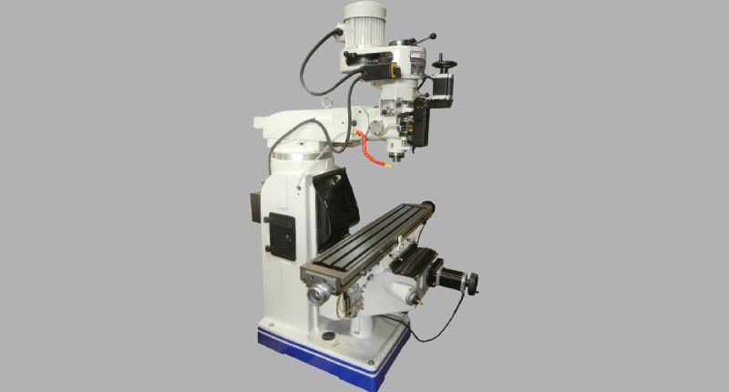
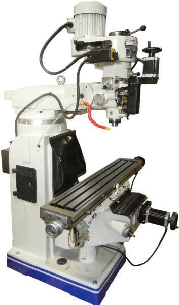
Also known as a variable-speed vertical milling machine, the knee mill uses cutting tools, such as end mills and face mills, to remove material from a workpiece. These cutting tools are held vertically, while the workpiece is clamped to a horizontal worktable or held in a secured vise for cutting.

The ā€œkneeā€ is a heavy-duty Meehanite casting that supports the worktable and rides vertically on a dovetail on the machineā€™s ā€œcolumn.ā€ The machineā€™s operator can raise or lower the table manually, allowing knee travel along the Z-axis, depending on the height of the workpiece.

Part of the versatility of the manual knee mill is that it can be used as a drill press. Drilling is possible because of the vertical knee millā€™s unique feature called a quill, which is part of the spindle motor and travels vertically, acting as a second Z-axis. Quill travel is enacted by a manual handle or automatic quill feed.

Other advantages of vertical milling machines are their relative simplicity and the fact they take up much less space than horizontal mills, their bulkier counterparts.

How Does a Knee Mill Work?

Although no one can argue against the virtues of CNC machines, CNC machining centers, or CNC knee mills, it’s also impossible to ignore the value the manual knee mill brings to the average machine or fab shop. A 3-axis CNC mill cannot always machine a workpiece completely, leaving secondary operations, like adding a single hole with threads that wouldn’t be worth re-setting on the CNC.

Knee mills bring simplicity and versatility to vertical machining. For example, it takes seconds to clamp a block to the knee mill’s table, drill and tap a few holes, or put a shaft in a vise and mill a keyway in the end. There is no need for time-consuming programming in these cases. And if your manual knee mill is equipped with an Acu-Rite digital readout (DRO), those holes or that keyway will be accurately positioned.

Most knee mills today have a power feed, at least on the left-to-right X-axis, making many milling operations quick and effortless. And with high-rpm spindle speeds, it’s possible to drill tiny holes or mill narrow slots without worrying about breaking cutters. You can also tackle larger workpieces since the milling machine spindle’s cutter head is attached to a movable ram that travels in and out and swivels for greater part coverage. Also, the cutter head can be set to any angle from horizontal to vertical for angular cuts and drilled holes.

On many machines, the saddle and knee (Y-axis) are moved by hand, while the worktable is either hand-cranked or power-driven, whichever is quicker. When you think about all those small operations machinists can do in support of the shop’s CNC machining centers, you recognize how indispensable manual knee mills are to the typical machine shop.

What is a Knee Mill Used For?

A vertical knee mill is a versatile machine tool allowing a machinist to perform various tasks, including face milling, slotting, drilling, and boring. Manual knee mills work well for prototyping, tool room work, repairs, general job shop work, and R&D work. Depending on the knee mill’s table size, it’s possible to mill and drill long workpieces, create fixtures, do minor rework, and complete once-and-done parts.

Many CNC shops keep manual knee mills on the shop floor to fill in gaps in the work schedule. For example, while a long run is on the CNC mill, a machinist can hop on the manual knee mill and work on a secondary operation, repair job, or any number of relatively small operations. And the same thing holds for having manual lathes in a shop with predominantly CNC lathes.

The manual knee mill’s versatility comes from its R8 spindle taper. Using an R8 collet as a tool holder, you can quickly change tooling from milling a flat surface to adding a few slots to drilling and tapping a hole in a workpiece. There’s no need to write a program or set up tooling in the CNC machine for small machining operations. The knee mill can also help machine larger objects thanks to the extra coverage from the movable ram.

What’s the Difference Between a Knee Mill and a Bed Mill?

At the risk of sounding redundant, the primary difference between a knee mill and a bed mill is the flexibility the knee mill provides. From a mechanical standpoint, the knee millā€™s table moves up and down on the Z-axis, while the bed millā€™s spindle moves up and down.

As mentioned earlier, knee mills have a ā€œquillā€ that acts as a second Z-axis and turns the knee milling machine into a drill press. The spinning quill moves up and down with a handle on the spindle head or an optional power feed.

Knee mills can do more things than bed mills. Here are a few examples:

Machining parts that exceed a milling machineā€™s travel is never easy, but with a knee mill, itā€™s at least possible to do it without moving the workpiece. You might be able to swivel the head, extend the ram on the knee mill, and reach areas that would be unreachable on a bed mill.

Tilting the head to machine an angle on a workpiece is routine on a knee mill.Ā  To make the same cut on a bed mill, you must set the workpiece at the correct angle, which could involve expensive fixtures or a complicated setup.

You have the option to attach long parts to an angle plate and hang them off the side of the knee millā€™s table for drilling or milling. Since you can swivel the head and extend the ram, you can reach beyond the table. On a bed mill, you need to attach the part to a tall angle plate to machine the end, assuming you have sufficient Z-travel to clear the piece.

Although knee mills can do more things than bed mills, if you are making lots of heavy cuts utilizing maximum horsepower, a bed mill may serve your needs better.

What is a Bridgeport Knee Mill?

In 1936, Rudolph Bannowā€™s company produced a ā€œknee-and-columnā€ vertical mill that featured a rotating turret and sliding-ram head. The company was named Bridgeport, and the unique milling machine took its name.

Over those eighty-plus years, the name became synonymous with durable quality machine tools and remained on a shop floor for decades. Today, other machine manufacturers have copied the design, and Bridgeport no longer owns the company, Hardinge having bought it several years ago.

However, most in the manufacturing industry still call it a Bridgeport (or at least a Bridgeport-type knee mill), regardless of its actual brand name. And even though CNC machining centers have become the darlings of the machining industryā€”and rightfully soā€”traditional knee mills have not faded and show no signs of doing so anytime soon.

How Do I Choose Between Buying a CNC Knee Mill and a Traditional Knee Mill?

supra knee mill
CNC Masters Supra Knee Mill

The good news is you donā€™t have to choose! The CNC Supra Vertical Knee Mill from CNC Masters has all the latest features to machine the most complex parts and high productivity. It also has hand-wheels on each axis for optional manual machining, allowing machinists to complete those quick operations that donā€™t require programming.

The Supra high-quality, USA-built knee mill with ball screws, a warranty, and excellent service, all at a competitive price! Please email us directly at sales@cncmasters.com, call us at 626-962-9300, or visit our contact page. We look forward to hearing from you!

About Peter Jacobs

Peter Jacobs is the Senior Director of Marketing at CNC Masters, a leading supplier of CNC mills, milling machines, and CNC lathes. He is actively involved in manufacturing processes and regularly contributes his insights for various blogs in CNC machining, 3D printing, rapid tooling, injection molding, metal casting, and manufacturing in general. You can connect with him on his LinkedIn.

Have Questions? Need a Quote?

Looking for more information about our CNC machines and services? Contact us today.

Contact

Slide 1

29. Create a Peck Drilling Program in Circular or Rectangular Patterns
Using the Circular or Rectangular Drilling Wizards, you can program the machine to drill an un-limited series of holes along the X and Y planes. Program it to drill straight through to your total depth, use a high-speed pecking cycle, or deep hole pecking cycle. You can program the cut-in depth and return point for a controlled peck drill application to maximize chip clearance.

Slide 1

20. Change up to 30 tools with compensation, and store your tool offsets for other programs
The MX supports…

Slide 1

21. Use the optional ATC rack up to 8 tools for milling, drilling, and rigid tapping applications
The CNC Masters Automatic Tool Changer Rack and Tools (US Patent 9,827,640B2) can be added to any CNC Masters Milling Machine built with the rigid tapping encoder option. The tutorial will guide you through the set-up procedure using the ATC tools.

Slide 1

22. Use the optional Rigid Tapping Wizard without the need for tapping head attachments
When you order your CNC Masters machine, have it built with the optional rigid tapping encoder. You can take any drill cycle program and replace the top line with a tapping code created by the wizard to tap your series of holes up to 1/2ā€ in diameter.

Slide 1

23. Use the optional Digital Probe to scan the profile and/or pockets of your fun/hobby type designs to write your tool path program and machine out a duplicate of your original design To ā€œsurfaceā€ scan an object, you can program the probe along the X or Y plane. The stylus will travel over the part starting on the left side front corner of the object and work its way to the end of the part on the right side. Depending on how the stylus moves, it will record linear and interpolated movements along the X, Y, and Z planes directly on the MX Editor.
To ā€œpocketā€ scan an object containing a closed pocket such as circles or squares, the scan will start from the top front, work its way inside of the pocket, and scan the entire perimeter of the pocket.
Under the Setup of the MX software you will find the Probe Tab which will allow you to calibrate and program your probe. Your ā€œProbe Stepā€, ā€œFeedā€, and ā€œData Filterā€ can also be changed on the fly while the probe is in the middle of scanning your object.

Slide 1

24. Use work offsets G54-G59 for nesting applications
The work offsets offer you a way to program up to six different machining locations. Itā€™s like having multiple 0.0 locations for different parts. This is very useful especially when using sub-routines/nesting applications.

Slide 1

25. Create a Rectangular Pocket / Slot with our selection of Wizards to help you build a tool path program
The Cycle Wizards for the mill or lathe makes it easy to create a simple tool path without needing to use a CAD and CAM software.
On this Wizard, the Rectangular Pocket / Slots, can be used to form a deep rectangular pocket into your material or machine a slot duplicating as many passes needed to its total depth.

Slide 1

26. Create a Circular Pocket Wizard
Input the total diameter, the step down, and total depth and the code will be generated.

Slide 1

27. Do Thread Milling using a single point cutter Wizard

Slide 1

28. Cut a gear out using the Cut Gear Wizard with the optional Fourth Axis

Slide 1

19. Disable the axis motors to manually hand crank each axis into place
Easily de-energize the axis motors by clicking [Disable Motors] to crank each axis by hand, and then press [Reset Control] to re-energize the axis motors.

Slide 1

30. The MX interface can easily be interchanged from Mill Mode to Lathe Mode
Use this interface for your CNC Masters Lathe. It contains all the same user-friendly features and functions that comes in Mill Mode. Simply go to the Setup page and change the interface.

Slide 1

31. Use Tool Change Compensation or the optional Auto Tool Changer Turret if your application requires more than one tool in a single program
You can offset the length and angle of each tool and record it under Tools in your Setup. The program will automatically pause the latheā€™s movement and spindle allowing you to change out your tool, or allowing the optional ATC Turret to quickly turn to its next tool and continue machining.
On the MX interface, you also have four Tool Position buttons. Select your desired T position, and the auto tool post will quickly turn and lock itself to that position.

Slide 1

32. Use the Lathe Wizard Threading Cycle to help you program your latheā€™s internal or external threads in inches or metric

Slide 1

33. Use the Lathe Wizard Turning / Boring Cycle to help you program simple turning and boring cycles without having to go through a CAM or writing a long program with multiple passes

Slide 1

34. Use the Lathe Wizard Peck Drilling Cycle to help you program your drill applications or for face grooving

Slide 1

35. Facing / Grooving / Part Off Cycle Wizards ā€“ with Constant Surface Speed
These cycles can be used with Constant Surface Speed allowing the spindle speed to increase automatically as the diameter of the part decreases giving your application a consistent workpiece finish. With CSS built into the wizard, there is no need to break down the cycle into multiple paths and multiple spindle speed changes.

Slide 1

36. This is our list of supported G and M codes which can be found under Tools > G Code/ M Code List in the MX
If you plan to use a third-party CAM software to generate your tool path program, use a generic FANUC post processor and edit it to match our list of codes. As an option, we also sell Visual mill/turn CAM software which comes with a guaranteed post processor for our machines to easily generate your tool path programs based on your CAD drawings.

Slide 1

37. Our pledge to you…

Slide 1

10. Run each tool path independently to study its movement
1. Run the machine on Trace mode. You can run each tool path independently, one line at a time to study the tool path movement on the machine to verify the position of the application and if any fixture/vise is in the way of the cutterā€™s path.

2. You can also verify your program by clicking on the Trace and Draw buttons together. This will allow you to view each tool path independently one line at a time in the Draw Window.

Slide 1

2. Clutter Free Interface
The MX is engineered for the CNC MASTERS machine so you do not have to fiddle with a detailed complicated configuration that can be overwhelming. Just load in the MX and start machining!2. Clutter Free Interface
The MX is engineered for the CNC MASTERS machine so you do not have to fiddle with a detailed complicated configuration that can be overwhelming. Just load in the MX and start machining!

Slide 1

3. Features Tour and Tutorials Included
The Features Tour will give you a quick run-down on all the features the MX can do for you. The Tutorials are easy to follow even for the first time CNC machinist.
Feel free to download the MX on any of your computers. We recommend downloading the MX along with your CAD and CAM software there at the comfort of your office computer to generate your tool path programs. You donā€™t need to be hooked up to the machine either to test your program in simulation mode.

Slide 1

4. Navigate and Edit Your Program through the MX interface with Ease
With a few clicks of the mouse or using touch screen technology, you can easily navigate through the MX interface importing saved programs into the Editor from the File drop down menu. Using standard windows features to edit your program you can then lock the Editor Screen to avoid accidental editing, and if you need to insert a line in the middle of a program, just click on [ReNum] to re-number your tool path list.
You can create a program or import CAM generated G-code tool paths into the Editor
The X Y and Z W arrow jog buttons are displayed from the point of view of the cutter to avoid confusion when the table and saddle are moving. You can also adjust your spindle speed and coolant control while jogging each axis.

Slide 1

5. Feed Hold ā€“ Pause in the Middle of your Program
Feed Hold lets you pause in the middle of a program. From there you can step through your program one line at time while opting to shut the spindle off and then resume your program.
You can also write PAUSE in the middle of your program and jog each axis independently while your program is in pause mode.

Slide 1

6. Hot Keys
Hot Keys is an alternative method to easily control your machine using your hard or touch screen keyboard. One can press P to pause a program, press S to turn Spindle On, G to run a program, Space Bar to Stop, J to record your individual movements one line at a time to create a program in teach mode.

Slide 1

7. Pick Menu ā€“ for conversational mode programming
Write FANUC style G-codes directly into the Editor or select commands off the [Pick] menu and write your tool path program in conversational mode such as what is written in the Editor box. You can even mix between conversation commands and G-codes in the same program.

Slide 1

8. Pick Menu List of Options
Use commands such as MOVE, SPINDLE ON/OFF, COOLANT ON/OFF, PAUSE, DELAY, GO HOMEā€¦. to write your tool path programs in conversational mode.

Slide 1

9. Draw the Tool Path to verify it before pressing Go
Hit Draw to view your tool path program drawing, check out its run time, or even simulate the tool path in 3D mode. This can be helpful to quickly verify your program before running it. You can also slow down or speed up the drawing or simulation process.
You can also hit Go within the Draw Window itself to verify the cutterā€™s position on the machine. The current tool path will be highlighted and simultaneously draw out the next path so you can verify what the cutter will be doing next on the program.

Slide 1

MX Software ā€“ Easy to Use, Easy to Learn ā€“ Included with your machine purchase
The MX software is designed to work seamlessly with your CNC Masters machine. It is made to work with Windows PC ā€“ desktop, laptop, or an all in one ā€“ on standard USB. Use it on Windows 8 or 10 64-bit operating systems.
No internal conversion printer/serial port to USB software or additional conversion hardware is used with the MX.

Slide 1

11. Counters display in Inches or Millimeters ā€“ Continuous Feed
1. When running a program, the counters will display a ā€œreal-timeā€ readout while the machine is in CNC operation without counting ahead of the movement.
2. The current tool path is highlighted while the machine is in operation without causing slight interruptions/pauses as the software feeds the tool path to the machine. The MX internally interprets a program ten lines ahead to allow for ā€œcontinuous machiningā€ avoiding slight interruptions as the machine waits for its next tool path command.
3. ā€œRun Timeā€ tells you how long it takes to run your tool path program.

Slide 1

12. Use the ā€œGo From Lineā€ command to start in the middle of your program
If you ever need to begin your program from somewhere in the middle of it, use [Go From Line] which you can find under Tools. The Help guide will walk you through how to position the cutter without losing its position on the machine.

Slide 1

13. Exact Motion Distance without over-stepping on an axis while jogging
Use ā€œRelative ONā€ to enter a specific coordinate to jog any of your axes to an exact location without having to write a program. Itā€™s like using ā€œpower feedā€ but easier. You can jog an exact distance on any of the axes without needing to keep the key pressed down and mistakenly over-step the movement releasing your finger too slowly off the jog button.
Letā€™s say you need to drill a hole exactly 0.525ā€ using the Z. So you enter 0.525 in the Z box. Next, adjust the JOG FEED RATE slider for the desired feed rate. Then ā€œclick onceā€ on the +Z or -Z button to activate the travel. In this case you click once the -Z button first to drill the hole exactly 0.525ā€. Then click once on the +Z button to drive the axis back up 0.525ā€.

Slide 1

14. Teach Mode ā€“ Jog Input
You can create a tool path program by storing each point-to-point movement by simply jogging an axis one at a time. Click on either of the Jog Input buttons to store each movement on the Editor Screen. You can then add Spindle ON, feed commands, and press GO to run the new program as needed. This is a great feature to help you learn to create a program by the movements you make on the machine without necessarily writing out an entire program first.

Slide 1

15. Override on the fly to adjust the Jog Feed to Rapid or the Spindle Speed during the middle of a program
1. Jog Feed and Rapid with Override: You can adjust feeds using the slider from slow minimum 0.1ā€³ per minute to a rapid of 100ā€³ per minute of travel. You can even micro-step your jog as low as 0.01ā€/min. The [-][+] buttons allow you to fine tune feeds in 5% increments while the program is in motion.
2. Spindle Speed with Override: You can adjust speeds using the slider from a slow minimum RPM to the max RPM according to the machine setup. The [-][+] buttons allow you to fine tune feeds in 5% increments while the program is in motion.

Slide 1

16. Adjust Counters using Pre-Set if you cannot begin the program from 0.00
In a situation where you cannot begin your cutter at itā€™s 0.00 location, you can ā€œPre-Setā€ directly into the counters by typing in your beginning coordinate. You can press Go from here to run your program. You can also ā€œzero allā€ or ā€œzeroā€ your counters independently. With one click of the [Return to 0.0] button, all axes will travel back to its respective 0.0 on the machine.

Slide 1

17. Set and Save your 0.00 position for future runs
Set and save your 0.00 position on the machine. These coordinates will be recorded as the first line of the program in the Editor Screen. Should you desire to return to this program at a later date, you only have to click on the Set Zero Return button. This will command the machine to automatically jog each axis to its saved ā€œsetā€ 0.00 position according to the recorded coordinates at the first line of the program.

Slide 1

18. Create a ā€œHomeā€ position to clear your application and run multiple times
Letā€™s say you need to machine one application times 100 pieces. This usually requires a jig to retain that physical 0.00 position. But in this case, you want the program to end with a clearance of the axes to easily switch out the next piece of stock and start again. With Save Home, you have the ability to save this offset (home) position while still retaining your Set Zero position where the machine will mill your part out. Pressing [Save Home] will record this new position under the Set Zero line in your program.
Pressing [Go Home] will jog your axes back to your ā€œsaved homeā€ position where you originally pressed the Save Home command. You can also input GO_HOME from the Pick Menu as its own tool path in your program. At the completion of your program the axes will end at your Home position. Replace your part, then press [Return to 0.0] button to allow the axes to return to its zero position, and press Go to start your next run.

previous arrow
next arrow