CALL US TODAY

CALL US TODAY

cnc machine coolant

What Type of CNC Coolant Should I Use?

Although few machine shops would completely disregard adding CNC coolant to their expensive machine tools, many donā€™t consider coolant systems as a primary component of their machining operations. However, the type of coolant you use and how you apply it is essential to metalworking success and an efficient machining process.

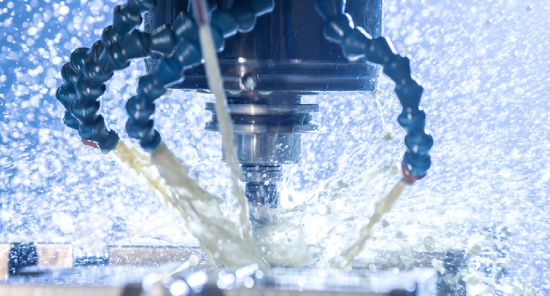
You can apply coolants and lubricants with compressed air, flood coolant, misting, or high pressure. Some machine shops choose CNC mills and lathes with minimum quantity lubrication (MQL) to minimize the amount of coolant used to avoid wasting it.

What is the Function of Coolant?

The terms ā€œcoolantā€ and ā€œlubricantā€ are often used interchangeably, but not all coolants are lubricants. For example, compressed air works as a coolant but has no use as a lubricant.

No matter what type of CNC machining you do, CNC coolants play a critical role. They help increase tool life and offer a better surface finish on the machined parts. By understanding the available coolant types, you can select a coolant that fits your machine and application. Maintaining the correct coolant concentrations also helps extend the life of your coolant, cutting tools, and CNC machine.Ā Ā 

Here are some of the ways cutting fluids benefits the machining process in your shop:

  • Reduce or remove the heat build-up between the cutting tool and workpiece since high temperatures can result in warping, melting, discoloration, or premature tool failure
  • Reduces friction with lubrication to aid the chip removal process
  • Evacuates chips and abrasives to clear the work area, preventing chip re-cutting and helping the partā€™s surface finish
  • Protects against corrosion

Remember that the type of coolant and the mix of cooling and lubrication will depend on the type of CNC machining and the materials you are cutting. Also, keep in mind that coolants can be expensive, and wasted coolant is wasted money. Knowing the amount and type of coolant required for the job can prevent this.

What is the Right Coolant for Your CNC Machine?

Using water alone as a coolant is never a good idea since itā€™s the additives in the fluid that prevent damaging rust and corrosion. Typically, most CNC machine tools use one of the following types of coolant classified as follows:

Soluble Oils

Soluble oils are the least expensive cutting fluids and the most common in machining operations. These so-called emulsions have excellent cooling and average lubricating properties. Soluble oils are created when mineral oil is added to water in specific percentages. Emulsifiers are also included to keep the solution mixed, while adding other components improves corrosion resistance, bacteria prevention, and lubrication. Soluble oils work best in light-cutting operations.

Synthetic Fluids

Synthetic fluids are water-based coolants containing organic and inorganic chemical compounds but no mineral oil. The additives in the fluid include lubricants, rust inhibitors, and corrosion inhibitors, all of which improve the other properties that the water content would have compromised.

One of the primary benefits of synthetic coolants is no foaming, which you typically find in fluids with high mineral oil content. So, when a synthetic coolant starts to foam, you know itā€™s contaminated.

Synthetic coolants are durable and more stable than other types of metalworking fluids. Their chemistry helps create solutions that reject all tramp oils and perform better in the sump, allowing for a longer-lasting solution with higher efficiency in recycling.

Although synthetic coolants cost more, the cost is offset by reduced consumption, such as lower amounts of concentration to recharge the solution.

Semi-Synthetic Fluids

Semi-synthetic fluids are a stable blend of mineral oil, corrosion inhibitors, and additives for a cleaner operation in high-speed and high-pressure CNC machines. They contain a mixture of up to 50% mineral oil, additives, and chemical compounds that dissolve in water. In other words, semi-synthetic fluids combine the properties of soluble oil and synthetic fluids.

Although they contain many of the same ingredients as soluble oils, semi-synthetic coolants are cleaner than soluble oils while providing excellent lubrication, heat reduction, rust control, and longer sump life.

Straight oils

Straight oils are not mixed into water and are made of a mineral or petroleum oil base. These fluids contain lubricants such as vegetable oils, fats, and esters, making them biodegradable and environmentally friendly. Unfortunately, they are expensive and decompose quickly. Because of this, they are primarily used as additives to petroleum and mineral oils to enhance their lubricating properties.

Straight oils often contain chlorine, phosphorus, and sulfur, extreme pressure additives that help reduce tool wear. Still, even though they provide the best lubrication, straight oils have the poorest cooling characteristics.

Find the Right Coolant Concentration

Most machine manufacturers provide explicit instructions on the type of coolant their machine requires. For instance, manufacturers of most 3-axis CNC machines provide detailed data on the necessary type of coolant and the coolantā€™s concentration level. Pay attention to the proportions they recommend and use deionized water when mixing the coolant solution since deionized water is typically non-corrosive to metals like aluminum and steel.

If the coolant is lower than the recommended concentration level, several issues can occur, including bacterial growth, reduced tool life, and corrosion to the machine and workpiece.

However, if the concentration of coolant is too high, you could experience any of the following:

  • Foaming
  • Less lubrication
  • Wasted coolant
  • Formation of residue that reduces tool life
  • Staining the machine and machined parts
  • Skin irritation (toxicity)

Machinists should check the coolant at the start of each day and maintain an acceptable concentration level. Hand refractometers are excellent for checking cutting fluid concentrations and maintaining control. Remember that machine coolant concentrations can change as much as 20% daily from evaporation, splashing, and misting. Therefore, a daily log of concentration levels for each CNC machine lets you know how the coolant system works and how much the concentration levels change from one day to the next.

Itā€™s essential to select the correct coolant for your machine and the metals youā€™re machining and to maintain the recommended concentration levels so that you can extend the life of the coolant, the cutting tools, and your CNC machine.

Machine Coolant Concentration Chart

Using the correct coolant for the material and type of machining results in higher production efficiency and sustained high-quality products. Recommendations vary according to the manufacturer, but for a general idea of different coolants used for other materials and machining operations, consider this machine coolant concentration chart from Fox Valley Technical College:

Material Milling Drilling Tapping Turning
Aluminum Soluble oil (96% water) or mineral oil Soluble oil (70-90% water) 25% sulfur-based oil mixed with mineral oil Mineral oil with 10% fat (or) soluble oil
Brass Soluble oil (96% water) Soluble oil 10-20% lard oil with mineral oil Mineral oil with 10% fat
Bronze Soluble oil Soluble oil 30% lard with mineral oil Soluble oil
Alloy Steels 10% lard oil with 90% mineral oil Soluble oil 30% lard oil with 70% mineral oil 25% sulfur base oil with 75% mineral oil
Cast Iron Dry Dry Dry or 25% lard oil with 80% mineral oil Dry
Malleable Iron Soluble oil Soluble oil Soluble oil Soluble oil
Copper Soluble oil Soluble oil Soluble oil Soluble oil
Low Carbon and Tool Steels Soluble oil Soluble oil 25-40% lard oil with mineral oil 25% lard oil with 75% mineral oil

Applying Water-Based Fluids and High-Pressure Coolants to CNC Machining

Applying a water-soluble cutting fluid is as vital as the type you use. Most CNC lathes and machining centers come with through-the-tool coolant capability, and it makes sense to use it, even if you must buy new tool holders.

If your machine tool can use high-pressure coolant (HPC), invest in a system and improve tool life, increase feeds and speeds, and eliminate issues with chip control. Unless you cut softer material like brass or free-machining cold-rolled steel most of the time, youā€™ll boost your bottom line with an HPC system. You could see up to 1,000 psi pressures, which are ideal for most operations, including deep-hole drilling and tapping.

Most machine shops observe longer tool life after they change cutting fluids, and thatā€™s because clean coolant has fewer bits of dirt and metal that contribute to tool wear. Understandably, you canā€™t empty the coolant tank, clean it, and add a fresh mixture every week, but using a filter is almost as effective.

Although synthetic or semi-synthetic fluids will cost more, there is a substantial payback in the form of higher productivity, longer tool life, and reduced cutting fluid consumption. Follow the best advice, match the cutting fluid to the material and operation, keep your coolant as clean as possible, apply the coolant effectively, and ensure you are using a high-quality sump pump.

Give Your Machining Coolant the Respect It Deserves

Too many machinists and machine shops take their CNC coolant for granted, and as a result, it has become one of the most overlooked components in a machining operation. CNC machining success and peak shop efficiency depend on the coolant or lubricant you use and the pressure you apply.

Remember that you can apply coolant as compressed air, misting, flooding it, or using a high-pressure system. Specific machine tools are MQL-able, meaning they can restrict the amount of coolant applied to only what is necessary, which avoids waste.

Coolants play an integral role in machining, including grinding, milling, drilling, and turning, and they are essential in prolonging tool life and providing improved surface finishes. Knowing the types of coolants and their correct application will help you select the proper coolant and the most beneficial one.

And finally, by properly maintaining the concentration levels of your coolant, you will extend the life of your coolant, along with your cutting tools and machine tool.

SOURCES:

https://wiki.thayer.dartmouth.edu/pages/viewrecentblogposts.action?key=machineshop&src=sidebar.

http://its.fvtc.edu/machshop1/coolant/cutfluids.htm.

https://van.physics.illinois.edu/qa/listing.php?id=17632.

http://www.phillipscorp.com/cnc-coolant-dos-donts/.

http://www.cnccookbook.com/CCCNCMillFeedsSpeedsCoolant.htm.

Have Questions? Need a Quote?

Looking for more information about our CNC machines and services? Contact us today.

Contact

Slide 1

29. Create a Peck Drilling Program in Circular or Rectangular Patterns
Using the Circular or Rectangular Drilling Wizards, you can program the machine to drill an un-limited series of holes along the X and Y planes. Program it to drill straight through to your total depth, use a high-speed pecking cycle, or deep hole pecking cycle. You can program the cut-in depth and return point for a controlled peck drill application to maximize chip clearance.

Slide 1

20. Change up to 30 tools with compensation, and store your tool offsets for other programs
The MX supports…

Slide 1

21. Use the optional ATC rack up to 8 tools for milling, drilling, and rigid tapping applications
The CNC Masters Automatic Tool Changer Rack and Tools (US Patent 9,827,640B2) can be added to any CNC Masters Milling Machine built with the rigid tapping encoder option. The tutorial will guide you through the set-up procedure using the ATC tools.

Slide 1

22. Use the optional Rigid Tapping Wizard without the need for tapping head attachments
When you order your CNC Masters machine, have it built with the optional rigid tapping encoder. You can take any drill cycle program and replace the top line with a tapping code created by the wizard to tap your series of holes up to 1/2ā€ in diameter.

Slide 1

23. Use the optional Digital Probe to scan the profile and/or pockets of your fun/hobby type designs to write your tool path program and machine out a duplicate of your original design To ā€œsurfaceā€ scan an object, you can program the probe along the X or Y plane. The stylus will travel over the part starting on the left side front corner of the object and work its way to the end of the part on the right side. Depending on how the stylus moves, it will record linear and interpolated movements along the X, Y, and Z planes directly on the MX Editor.
To ā€œpocketā€ scan an object containing a closed pocket such as circles or squares, the scan will start from the top front, work its way inside of the pocket, and scan the entire perimeter of the pocket.
Under the Setup of the MX software you will find the Probe Tab which will allow you to calibrate and program your probe. Your ā€œProbe Stepā€, ā€œFeedā€, and ā€œData Filterā€ can also be changed on the fly while the probe is in the middle of scanning your object.

Slide 1

24. Use work offsets G54-G59 for nesting applications
The work offsets offer you a way to program up to six different machining locations. Itā€™s like having multiple 0.0 locations for different parts. This is very useful especially when using sub-routines/nesting applications.

Slide 1

25. Create a Rectangular Pocket / Slot with our selection of Wizards to help you build a tool path program
The Cycle Wizards for the mill or lathe makes it easy to create a simple tool path without needing to use a CAD and CAM software.
On this Wizard, the Rectangular Pocket / Slots, can be used to form a deep rectangular pocket into your material or machine a slot duplicating as many passes needed to its total depth.

Slide 1

26. Create a Circular Pocket Wizard
Input the total diameter, the step down, and total depth and the code will be generated.

Slide 1

27. Do Thread Milling using a single point cutter Wizard

Slide 1

28. Cut a gear out using the Cut Gear Wizard with the optional Fourth Axis

Slide 1

19. Disable the axis motors to manually hand crank each axis into place
Easily de-energize the axis motors by clicking [Disable Motors] to crank each axis by hand, and then press [Reset Control] to re-energize the axis motors.

Slide 1

30. The MX interface can easily be interchanged from Mill Mode to Lathe Mode
Use this interface for your CNC Masters Lathe. It contains all the same user-friendly features and functions that comes in Mill Mode. Simply go to the Setup page and change the interface.

Slide 1

31. Use Tool Change Compensation or the optional Auto Tool Changer Turret if your application requires more than one tool in a single program
You can offset the length and angle of each tool and record it under Tools in your Setup. The program will automatically pause the latheā€™s movement and spindle allowing you to change out your tool, or allowing the optional ATC Turret to quickly turn to its next tool and continue machining.
On the MX interface, you also have four Tool Position buttons. Select your desired T position, and the auto tool post will quickly turn and lock itself to that position.

Slide 1

32. Use the Lathe Wizard Threading Cycle to help you program your latheā€™s internal or external threads in inches or metric

Slide 1

33. Use the Lathe Wizard Turning / Boring Cycle to help you program simple turning and boring cycles without having to go through a CAM or writing a long program with multiple passes

Slide 1

34. Use the Lathe Wizard Peck Drilling Cycle to help you program your drill applications or for face grooving

Slide 1

35. Facing / Grooving / Part Off Cycle Wizards ā€“ with Constant Surface Speed
These cycles can be used with Constant Surface Speed allowing the spindle speed to increase automatically as the diameter of the part decreases giving your application a consistent workpiece finish. With CSS built into the wizard, there is no need to break down the cycle into multiple paths and multiple spindle speed changes.

Slide 1

36. This is our list of supported G and M codes which can be found under Tools > G Code/ M Code List in the MX
If you plan to use a third-party CAM software to generate your tool path program, use a generic FANUC post processor and edit it to match our list of codes. As an option, we also sell Visual mill/turn CAM software which comes with a guaranteed post processor for our machines to easily generate your tool path programs based on your CAD drawings.

Slide 1

37. Our pledge to you…

Slide 1

10. Run each tool path independently to study its movement
1. Run the machine on Trace mode. You can run each tool path independently, one line at a time to study the tool path movement on the machine to verify the position of the application and if any fixture/vise is in the way of the cutterā€™s path.

2. You can also verify your program by clicking on the Trace and Draw buttons together. This will allow you to view each tool path independently one line at a time in the Draw Window.

Slide 1

2. Clutter Free Interface
The MX is engineered for the CNC MASTERS machine so you do not have to fiddle with a detailed complicated configuration that can be overwhelming. Just load in the MX and start machining!2. Clutter Free Interface
The MX is engineered for the CNC MASTERS machine so you do not have to fiddle with a detailed complicated configuration that can be overwhelming. Just load in the MX and start machining!

Slide 1

3. Features Tour and Tutorials Included
The Features Tour will give you a quick run-down on all the features the MX can do for you. The Tutorials are easy to follow even for the first time CNC machinist.
Feel free to download the MX on any of your computers. We recommend downloading the MX along with your CAD and CAM software there at the comfort of your office computer to generate your tool path programs. You donā€™t need to be hooked up to the machine either to test your program in simulation mode.

Slide 1

4. Navigate and Edit Your Program through the MX interface with Ease
With a few clicks of the mouse or using touch screen technology, you can easily navigate through the MX interface importing saved programs into the Editor from the File drop down menu. Using standard windows features to edit your program you can then lock the Editor Screen to avoid accidental editing, and if you need to insert a line in the middle of a program, just click on [ReNum] to re-number your tool path list.
You can create a program or import CAM generated G-code tool paths into the Editor
The X Y and Z W arrow jog buttons are displayed from the point of view of the cutter to avoid confusion when the table and saddle are moving. You can also adjust your spindle speed and coolant control while jogging each axis.

Slide 1

5. Feed Hold ā€“ Pause in the Middle of your Program
Feed Hold lets you pause in the middle of a program. From there you can step through your program one line at time while opting to shut the spindle off and then resume your program.
You can also write PAUSE in the middle of your program and jog each axis independently while your program is in pause mode.

Slide 1

6. Hot Keys
Hot Keys is an alternative method to easily control your machine using your hard or touch screen keyboard. One can press P to pause a program, press S to turn Spindle On, G to run a program, Space Bar to Stop, J to record your individual movements one line at a time to create a program in teach mode.

Slide 1

7. Pick Menu ā€“ for conversational mode programming
Write FANUC style G-codes directly into the Editor or select commands off the [Pick] menu and write your tool path program in conversational mode such as what is written in the Editor box. You can even mix between conversation commands and G-codes in the same program.

Slide 1

8. Pick Menu List of Options
Use commands such as MOVE, SPINDLE ON/OFF, COOLANT ON/OFF, PAUSE, DELAY, GO HOMEā€¦. to write your tool path programs in conversational mode.

Slide 1

9. Draw the Tool Path to verify it before pressing Go
Hit Draw to view your tool path program drawing, check out its run time, or even simulate the tool path in 3D mode. This can be helpful to quickly verify your program before running it. You can also slow down or speed up the drawing or simulation process.
You can also hit Go within the Draw Window itself to verify the cutterā€™s position on the machine. The current tool path will be highlighted and simultaneously draw out the next path so you can verify what the cutter will be doing next on the program.

Slide 1

MX Software ā€“ Easy to Use, Easy to Learn ā€“ Included with your machine purchase
The MX software is designed to work seamlessly with your CNC Masters machine. It is made to work with Windows PC ā€“ desktop, laptop, or an all in one ā€“ on standard USB. Use it on Windows 8 or 10 64-bit operating systems.
No internal conversion printer/serial port to USB software or additional conversion hardware is used with the MX.

Slide 1

11. Counters display in Inches or Millimeters ā€“ Continuous Feed
1. When running a program, the counters will display a ā€œreal-timeā€ readout while the machine is in CNC operation without counting ahead of the movement.
2. The current tool path is highlighted while the machine is in operation without causing slight interruptions/pauses as the software feeds the tool path to the machine. The MX internally interprets a program ten lines ahead to allow for ā€œcontinuous machiningā€ avoiding slight interruptions as the machine waits for its next tool path command.
3. ā€œRun Timeā€ tells you how long it takes to run your tool path program.

Slide 1

12. Use the ā€œGo From Lineā€ command to start in the middle of your program
If you ever need to begin your program from somewhere in the middle of it, use [Go From Line] which you can find under Tools. The Help guide will walk you through how to position the cutter without losing its position on the machine.

Slide 1

13. Exact Motion Distance without over-stepping on an axis while jogging
Use ā€œRelative ONā€ to enter a specific coordinate to jog any of your axes to an exact location without having to write a program. Itā€™s like using ā€œpower feedā€ but easier. You can jog an exact distance on any of the axes without needing to keep the key pressed down and mistakenly over-step the movement releasing your finger too slowly off the jog button.
Letā€™s say you need to drill a hole exactly 0.525ā€ using the Z. So you enter 0.525 in the Z box. Next, adjust the JOG FEED RATE slider for the desired feed rate. Then ā€œclick onceā€ on the +Z or -Z button to activate the travel. In this case you click once the -Z button first to drill the hole exactly 0.525ā€. Then click once on the +Z button to drive the axis back up 0.525ā€.

Slide 1

14. Teach Mode ā€“ Jog Input
You can create a tool path program by storing each point-to-point movement by simply jogging an axis one at a time. Click on either of the Jog Input buttons to store each movement on the Editor Screen. You can then add Spindle ON, feed commands, and press GO to run the new program as needed. This is a great feature to help you learn to create a program by the movements you make on the machine without necessarily writing out an entire program first.

Slide 1

15. Override on the fly to adjust the Jog Feed to Rapid or the Spindle Speed during the middle of a program
1. Jog Feed and Rapid with Override: You can adjust feeds using the slider from slow minimum 0.1ā€³ per minute to a rapid of 100ā€³ per minute of travel. You can even micro-step your jog as low as 0.01ā€/min. The [-][+] buttons allow you to fine tune feeds in 5% increments while the program is in motion.
2. Spindle Speed with Override: You can adjust speeds using the slider from a slow minimum RPM to the max RPM according to the machine setup. The [-][+] buttons allow you to fine tune feeds in 5% increments while the program is in motion.

Slide 1

16. Adjust Counters using Pre-Set if you cannot begin the program from 0.00
In a situation where you cannot begin your cutter at itā€™s 0.00 location, you can ā€œPre-Setā€ directly into the counters by typing in your beginning coordinate. You can press Go from here to run your program. You can also ā€œzero allā€ or ā€œzeroā€ your counters independently. With one click of the [Return to 0.0] button, all axes will travel back to its respective 0.0 on the machine.

Slide 1

17. Set and Save your 0.00 position for future runs
Set and save your 0.00 position on the machine. These coordinates will be recorded as the first line of the program in the Editor Screen. Should you desire to return to this program at a later date, you only have to click on the Set Zero Return button. This will command the machine to automatically jog each axis to its saved ā€œsetā€ 0.00 position according to the recorded coordinates at the first line of the program.

Slide 1

18. Create a ā€œHomeā€ position to clear your application and run multiple times
Letā€™s say you need to machine one application times 100 pieces. This usually requires a jig to retain that physical 0.00 position. But in this case, you want the program to end with a clearance of the axes to easily switch out the next piece of stock and start again. With Save Home, you have the ability to save this offset (home) position while still retaining your Set Zero position where the machine will mill your part out. Pressing [Save Home] will record this new position under the Set Zero line in your program.
Pressing [Go Home] will jog your axes back to your ā€œsaved homeā€ position where you originally pressed the Save Home command. You can also input GO_HOME from the Pick Menu as its own tool path in your program. At the completion of your program the axes will end at your Home position. Replace your part, then press [Return to 0.0] button to allow the axes to return to its zero position, and press Go to start your next run.

previous arrow
next arrow