CALL US TODAY

CALL US TODAY

cnc machinist using the cnc masters mini mill baron milling machine

11 Features The Best Mini Milling Machines All Have in Common

Not too long ago, the idea of a hobbyist, do-it-yourselfer (DIY), or machinist working from a garage or workshop would have a milling machine, let alone a CNC mill, was a foreign notion. After all, even a small milling machine like a Bridgeport vertical mill was likely well beyond their budgets, and the floor space required for a typical mill was not available in their confined working area.

However, the advent of micro-mills (a.k.a. mini-mills, benchtop, and desktop mills) has allowed practically anyone access to high-precision machining. Add a mini-lathe, drill chuck, and various end mills, and owning a machine shop with a relatively inexpensive investment is possible. And as more entrepreneurs try their hands at manual and CNC milling, a new crop of machine tools is popping up to meet those needs.

But mini-mills are like fingerprints or snowflakes in that no two are alike. So, finding a milling machine thatā€™s right for you can be challenging. We can help by showing you what to look for as you begin your search and to avoid those inevitable pitfalls.

But first, letā€™s ensure you clearly understand what defines a mini milling machine and its common uses.

What is a Mini Milling Machine?

A mini milling machine is a smaller version of a full-sized milling machine without all its features. The mills are manufactured under brand names that might be unfamiliar, such as Proxxon, Grizzly, Jet, and the Klutch Mini Milling Machine. Available from Amazon and designed to produce small parts in shops with limited space and budgets, some models offer helpful features while others have few. Itā€™s essential to shop carefully since the specifications for these mills differ considerably. Here are a few examples:

Table size: 3-5/8ā€³ x 15-3/4ā€³ up to 4.7ā€³ x 18.1ā€³

X and Y-axis travel: 7-5/16ā€ x 4ā€ up to 11.8ā€ x 5.1ā€

Spindle taper: R8 collets or #3 Morse taper

Head tilt: Solid column (no tilt) vs. tilting headstock (45Ā° in either direction)

Horsepower: 0.47 HP (350W motor) vs. 0.67 HP (500W motor)

Weight: 18.1 pounds (Proxxon Micro Mill) vs. 440 pounds (Jet Mill-Drill)

Although most mini-mills operate under 110-volt household current, some might require an upgrade to 220V. Also, remember that machines weighing less than 100 pounds will be more portable than their heavier counterparts. Still, the heavy-duty cast iron models will allow for deeper cuts and tougher metal machining without vibration.

What are the Primary Applications for a Mini Metal-Working Machine?

Many mini-mill operations will entail machining small parts and components, which are not usually clamped directly to the worktable using clamps in the t-slots. Because of this, a high-quality vise should be one of your first purchases.

While holding the workpiece securely, you can do face milling, slot milling with end mills, or other functions with various cutting tools. You can also take advantage of the machineā€™s drilling capacity by using it as a variable speed control drill press.

If youā€™re anticipating precision milling or placing holes in your workpiece accurately with your drilling machine, consider adding a digital readout (DRO) to make that possible. Also, remember that all your milling operations will be faster and more efficient with a power feed on the X-axis.

One final suggestion: if you still need to buy a metal lathe for your shop, a rotary table can be a cheaper option for machining round work.

What are the Differences between a Mini Mill and a Regular-Sized Mill?

Although manufacturers often market mini-milling machines as miniature versions of full-sized industrial machine tools in large factories, thatā€™s not the whole story. Mini milling is ideal for DIY enthusiasts and freelance machinists working on smaller parts, but their table size and reduced horsepower limit the projects they can accomplish with them.

A standard Bridgeport-style vertical knee mill weighs about 2,000 to 3,000 lbs. with considerably more travel on all three axes. They can withstand deeper cuts and faster feed rates without a hint of vibration. As mentioned, some smaller mini-mills weigh over 400 pounds while others weigh less than a quarter of that, limiting their efficiency. Most of their motors generate about 1/2 horsepower, while a 2J Bridgeport head has a 3-HP motor.

Unfortunately, a full-sized milling machine is not an option for those working from their basement, garage, or small workshop. The footprint or the height of a standard-sized milling machine eliminates it from consideration. So, a high-quality mini-mill is the hands-down winner regarding floor space, price, and portability.

Despite the price, weight, and capability differences, both machine types offer similar machining methods, including using carbide and high-speed steel (HSS) cutting tools, the ability to use the mini-mill as a drill press, and the flexibility to machine various materials and turn it into a woodworking machine, for instance.

Must-Have Features of Mini Milling Machines

1. CNC Machining Capability

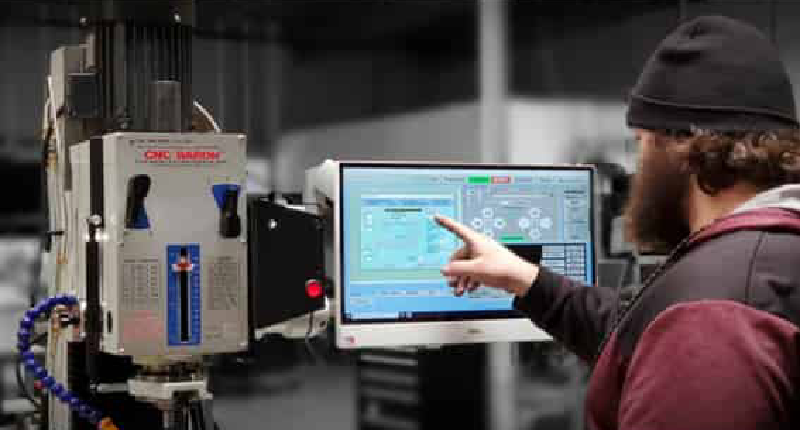
If you want to take advantage of your machineā€™s potential, consider a CNC milling machine over a standard mini-mill. Although CNC automation might initially sound intimidating, modern CNC machine tools are more user-friendly, making them easier to learn and operate. And the benefits they provide will far outweigh any learning curve you experience.

2. Versatility

Although CNC capability expands your work on your mini-mill, sometimes you must drill a few holes or add a milled slot. Having a machine that seamlessly converts from CNC mode to manual operations and back again is an invaluable feature.

The three desktop milling machine models fromĀ CNC MastersĀ come with hand wheels on each axis for manual machining. The mills have a ā€œmotor disengageā€ feature that retains computer spindle speed control for the machine.

3. Dovetail Ways

For accurate alignment and movements, any mini-mill should have hand-scraped dovetail ways with tapered gibs on the column, X-axis table, and Y-axis saddle.

4. Table Size and Machine Weight

Mini-milling machines come in various sizes, and buying a low-priced tiny machine might be tempting. However, it might not meet your needs since it will limit the projects you can take on. Furthermore, only some cheap, lightweight mills are typically built to last. Remember, larger mini-milling machines enable you to work on more projects, and heavier models have a sturdier base to enhance accuracy and precision.

The lineup of desktop milling machines from CNC Masters has generous table travels of up toĀ 21.5ā€ on the X-axis and 10.5ā€ on the Y-axis. The machines weigh from 700 to 900 lbs., but their small footprints make them ideal for those working with limited floor space.

5. Sufficient Power

Depending on your machining goals, power is critical to consider before buying a milling machine. The mini-millā€™s power determines which projects it can handle. For example, if you plan to machine stainless steel, you need a powerful machine. Any steel requires relatively high horsepower, and a 1/2 horsepower machine will struggle to cut it.

Unless you intend to confine your applications to woodworking, look for a machine delivering two horsepower from its spindle, so you can efficiently machine any material that comes your way.

6. High-Speed Spindle

Spindle speed is another critical factor to consider when buying a mini-mill. Because various materials require different speeds, ensure that the machine you choose has variable speeds up to 4500 RPMs so you have convenient speed adjustments to match the material and the workpieceā€™s requirements.

7. Vibration-Free Operation

If high precision and accuracy are essential, look for a machine tool with a sturdy base. The best mini-mills are vibration-free and manufactured from cast iron, which absorbs vibrations and lasts indefinitely. Cast iron is heavy, so eliminate any products weighing 100 to 200 pounds. They will disappoint you if you want accuracy, durability, and no vibration from your machine.

8. Competitive Price

One of the primary reasons for buying a mini-mill is to save money. Even used full-sized milling machines come with a hefty price tag, especially CNC mills. And even though some mini-mills come with a ā€œbargain-basementā€ price, you must consider your needs, and if they include CNC machining, 3D surface milling, and mold making, a 3-axis CNC tabletop mill with user-friendly software could be a perfect fit for you.

The good news is that you can have a mill that fits the criteria for under $6,000. The multipurpose CNC Jr. Benchtop Milling Machine from CNC Masters has a rugged cast iron base, G-CODE file interpreter, X & Y ball screws with pre-loaded ball nuts, and a CNC Control Unit starting a $5,893!

9. Digital Readout (DRO)

If you want to improve your machining efficiency, consider adding a digital readout to your mini-mill. A DRO displays the cutting toolā€™s X, Y, and Z positions in inches or metric, so you wonā€™t misread handwheel dials or lose count of the wheel rotations, reducing costly and frustrating mistakes. They provide accuracy for milling machines, lathes, and other machine shop equipment while improving your productivity and the quality of your work.

10. Power Feed

If you anticipate lots of milling work, having a power feed on the X-axis of your mill is a must. Not only will you avoid hand-cranking the cutter through several long passes, but a rapid-traverse feature will return the tool to its starting pointā€”all at the press of a button!

11. Warranty and Service

Even the best benchtop mill needs occasional repair. If that happens soon after you buy the machine, a warranty protects you against a surprise expense. A reputable manufacturer will include a one-year warranty with the option to purchase extra years.

Also, the money you saved on that lightweight mini-mill will quickly disappear if you must pay for troubleshooting or help with setup issues. CNC Masters provides unlimited ā€œlife-longā€ operational tech support with step-by-step troubleshooting and a walk-through process by email or phone!

A Mini-Milling Machine Meeting All the Requirements-

The CNC Baron Mini Milling Machine

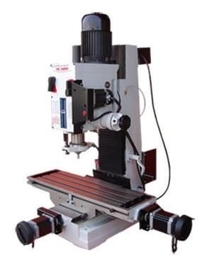
The CNC Baron desktop milling machine, manufactured by CNC Masters, is at home in every machining environment. Ideal for the hobbyist or machinist producing one part at a time or the large facility involved in mass production, the Baron can do it all without taking about lots of floor space or requiring complicated and expensive operating software. Here are only a few of its primary attributes:

  • Generous table travel (21.5ā€ on the X-axis and 10.5ā€ on the Y-axis)
  • Dovetailed column
  • Vibration-free operation (this 900-pound workhorse will not dance across your shop)
  • 2-HP spindle motor (no worries about stalling the cutting tool when machining steel)
  • Handwheels for manual operation
  • Ballscrews on the X and Y axes
  • One-shot oil lubricant
  • User-friendly operating software (included)
  • Excellent warranty
  • Unlimited ā€œLife-Longā€ tech support (for as long as your company owns the Baron)
  • Made in the USA
  • And many other features.

The rugged cast-iron Baron is built to last. It is not a hobby machine but a serious machine tool built for hobbyists and professionals. Talk to an expert at CNC Masters to discover all the benefits this versatile machine can provide you!

About Peter Jacobs

Peter Jacobs is the Senior Director of Marketing at CNC Masters, a leading supplier of CNC mills, milling machines, and CNC lathes. He is actively involved in manufacturing processes and regularly contributes his insights for various blogs in CNC machining, 3D printing, rapid tooling, injection molding, metal casting, and manufacturing in general. You can connect with him on his LinkedIn.

Have Questions? Need a Quote?

Looking for more information about our CNC machines and services? Contact us today.

Contact

Slide 1

29. Create a Peck Drilling Program in Circular or Rectangular Patterns
Using the Circular or Rectangular Drilling Wizards, you can program the machine to drill an un-limited series of holes along the X and Y planes. Program it to drill straight through to your total depth, use a high-speed pecking cycle, or deep hole pecking cycle. You can program the cut-in depth and return point for a controlled peck drill application to maximize chip clearance.

Slide 1

20. Change up to 30 tools with compensation, and store your tool offsets for other programs
The MX supports…

Slide 1

21. Use the optional ATC rack up to 8 tools for milling, drilling, and rigid tapping applications
The CNC Masters Automatic Tool Changer Rack and Tools (US Patent 9,827,640B2) can be added to any CNC Masters Milling Machine built with the rigid tapping encoder option. The tutorial will guide you through the set-up procedure using the ATC tools.

Slide 1

22. Use the optional Rigid Tapping Wizard without the need for tapping head attachments
When you order your CNC Masters machine, have it built with the optional rigid tapping encoder. You can take any drill cycle program and replace the top line with a tapping code created by the wizard to tap your series of holes up to 1/2ā€ in diameter.

Slide 1

23. Use the optional Digital Probe to scan the profile and/or pockets of your fun/hobby type designs to write your tool path program and machine out a duplicate of your original design To ā€œsurfaceā€ scan an object, you can program the probe along the X or Y plane. The stylus will travel over the part starting on the left side front corner of the object and work its way to the end of the part on the right side. Depending on how the stylus moves, it will record linear and interpolated movements along the X, Y, and Z planes directly on the MX Editor.
To ā€œpocketā€ scan an object containing a closed pocket such as circles or squares, the scan will start from the top front, work its way inside of the pocket, and scan the entire perimeter of the pocket.
Under the Setup of the MX software you will find the Probe Tab which will allow you to calibrate and program your probe. Your ā€œProbe Stepā€, ā€œFeedā€, and ā€œData Filterā€ can also be changed on the fly while the probe is in the middle of scanning your object.

Slide 1

24. Use work offsets G54-G59 for nesting applications
The work offsets offer you a way to program up to six different machining locations. Itā€™s like having multiple 0.0 locations for different parts. This is very useful especially when using sub-routines/nesting applications.

Slide 1

25. Create a Rectangular Pocket / Slot with our selection of Wizards to help you build a tool path program
The Cycle Wizards for the mill or lathe makes it easy to create a simple tool path without needing to use a CAD and CAM software.
On this Wizard, the Rectangular Pocket / Slots, can be used to form a deep rectangular pocket into your material or machine a slot duplicating as many passes needed to its total depth.

Slide 1

26. Create a Circular Pocket Wizard
Input the total diameter, the step down, and total depth and the code will be generated.

Slide 1

27. Do Thread Milling using a single point cutter Wizard

Slide 1

28. Cut a gear out using the Cut Gear Wizard with the optional Fourth Axis

Slide 1

19. Disable the axis motors to manually hand crank each axis into place
Easily de-energize the axis motors by clicking [Disable Motors] to crank each axis by hand, and then press [Reset Control] to re-energize the axis motors.

Slide 1

30. The MX interface can easily be interchanged from Mill Mode to Lathe Mode
Use this interface for your CNC Masters Lathe. It contains all the same user-friendly features and functions that comes in Mill Mode. Simply go to the Setup page and change the interface.

Slide 1

31. Use Tool Change Compensation or the optional Auto Tool Changer Turret if your application requires more than one tool in a single program
You can offset the length and angle of each tool and record it under Tools in your Setup. The program will automatically pause the latheā€™s movement and spindle allowing you to change out your tool, or allowing the optional ATC Turret to quickly turn to its next tool and continue machining.
On the MX interface, you also have four Tool Position buttons. Select your desired T position, and the auto tool post will quickly turn and lock itself to that position.

Slide 1

32. Use the Lathe Wizard Threading Cycle to help you program your latheā€™s internal or external threads in inches or metric

Slide 1

33. Use the Lathe Wizard Turning / Boring Cycle to help you program simple turning and boring cycles without having to go through a CAM or writing a long program with multiple passes

Slide 1

34. Use the Lathe Wizard Peck Drilling Cycle to help you program your drill applications or for face grooving

Slide 1

35. Facing / Grooving / Part Off Cycle Wizards ā€“ with Constant Surface Speed
These cycles can be used with Constant Surface Speed allowing the spindle speed to increase automatically as the diameter of the part decreases giving your application a consistent workpiece finish. With CSS built into the wizard, there is no need to break down the cycle into multiple paths and multiple spindle speed changes.

Slide 1

36. This is our list of supported G and M codes which can be found under Tools > G Code/ M Code List in the MX
If you plan to use a third-party CAM software to generate your tool path program, use a generic FANUC post processor and edit it to match our list of codes. As an option, we also sell Visual mill/turn CAM software which comes with a guaranteed post processor for our machines to easily generate your tool path programs based on your CAD drawings.

Slide 1

37. Our pledge to you…

Slide 1

10. Run each tool path independently to study its movement
1. Run the machine on Trace mode. You can run each tool path independently, one line at a time to study the tool path movement on the machine to verify the position of the application and if any fixture/vise is in the way of the cutterā€™s path.

2. You can also verify your program by clicking on the Trace and Draw buttons together. This will allow you to view each tool path independently one line at a time in the Draw Window.

Slide 1

2. Clutter Free Interface
The MX is engineered for the CNC MASTERS machine so you do not have to fiddle with a detailed complicated configuration that can be overwhelming. Just load in the MX and start machining!2. Clutter Free Interface
The MX is engineered for the CNC MASTERS machine so you do not have to fiddle with a detailed complicated configuration that can be overwhelming. Just load in the MX and start machining!

Slide 1

3. Features Tour and Tutorials Included
The Features Tour will give you a quick run-down on all the features the MX can do for you. The Tutorials are easy to follow even for the first time CNC machinist.
Feel free to download the MX on any of your computers. We recommend downloading the MX along with your CAD and CAM software there at the comfort of your office computer to generate your tool path programs. You donā€™t need to be hooked up to the machine either to test your program in simulation mode.

Slide 1

4. Navigate and Edit Your Program through the MX interface with Ease
With a few clicks of the mouse or using touch screen technology, you can easily navigate through the MX interface importing saved programs into the Editor from the File drop down menu. Using standard windows features to edit your program you can then lock the Editor Screen to avoid accidental editing, and if you need to insert a line in the middle of a program, just click on [ReNum] to re-number your tool path list.
You can create a program or import CAM generated G-code tool paths into the Editor
The X Y and Z W arrow jog buttons are displayed from the point of view of the cutter to avoid confusion when the table and saddle are moving. You can also adjust your spindle speed and coolant control while jogging each axis.

Slide 1

5. Feed Hold ā€“ Pause in the Middle of your Program
Feed Hold lets you pause in the middle of a program. From there you can step through your program one line at time while opting to shut the spindle off and then resume your program.
You can also write PAUSE in the middle of your program and jog each axis independently while your program is in pause mode.

Slide 1

6. Hot Keys
Hot Keys is an alternative method to easily control your machine using your hard or touch screen keyboard. One can press P to pause a program, press S to turn Spindle On, G to run a program, Space Bar to Stop, J to record your individual movements one line at a time to create a program in teach mode.

Slide 1

7. Pick Menu ā€“ for conversational mode programming
Write FANUC style G-codes directly into the Editor or select commands off the [Pick] menu and write your tool path program in conversational mode such as what is written in the Editor box. You can even mix between conversation commands and G-codes in the same program.

Slide 1

8. Pick Menu List of Options
Use commands such as MOVE, SPINDLE ON/OFF, COOLANT ON/OFF, PAUSE, DELAY, GO HOMEā€¦. to write your tool path programs in conversational mode.

Slide 1

9. Draw the Tool Path to verify it before pressing Go
Hit Draw to view your tool path program drawing, check out its run time, or even simulate the tool path in 3D mode. This can be helpful to quickly verify your program before running it. You can also slow down or speed up the drawing or simulation process.
You can also hit Go within the Draw Window itself to verify the cutterā€™s position on the machine. The current tool path will be highlighted and simultaneously draw out the next path so you can verify what the cutter will be doing next on the program.

Slide 1

MX Software ā€“ Easy to Use, Easy to Learn ā€“ Included with your machine purchase
The MX software is designed to work seamlessly with your CNC Masters machine. It is made to work with Windows PC ā€“ desktop, laptop, or an all in one ā€“ on standard USB. Use it on Windows 8 or 10 64-bit operating systems.
No internal conversion printer/serial port to USB software or additional conversion hardware is used with the MX.

Slide 1

11. Counters display in Inches or Millimeters ā€“ Continuous Feed
1. When running a program, the counters will display a ā€œreal-timeā€ readout while the machine is in CNC operation without counting ahead of the movement.
2. The current tool path is highlighted while the machine is in operation without causing slight interruptions/pauses as the software feeds the tool path to the machine. The MX internally interprets a program ten lines ahead to allow for ā€œcontinuous machiningā€ avoiding slight interruptions as the machine waits for its next tool path command.
3. ā€œRun Timeā€ tells you how long it takes to run your tool path program.

Slide 1

12. Use the ā€œGo From Lineā€ command to start in the middle of your program
If you ever need to begin your program from somewhere in the middle of it, use [Go From Line] which you can find under Tools. The Help guide will walk you through how to position the cutter without losing its position on the machine.

Slide 1

13. Exact Motion Distance without over-stepping on an axis while jogging
Use ā€œRelative ONā€ to enter a specific coordinate to jog any of your axes to an exact location without having to write a program. Itā€™s like using ā€œpower feedā€ but easier. You can jog an exact distance on any of the axes without needing to keep the key pressed down and mistakenly over-step the movement releasing your finger too slowly off the jog button.
Letā€™s say you need to drill a hole exactly 0.525ā€ using the Z. So you enter 0.525 in the Z box. Next, adjust the JOG FEED RATE slider for the desired feed rate. Then ā€œclick onceā€ on the +Z or -Z button to activate the travel. In this case you click once the -Z button first to drill the hole exactly 0.525ā€. Then click once on the +Z button to drive the axis back up 0.525ā€.

Slide 1

14. Teach Mode ā€“ Jog Input
You can create a tool path program by storing each point-to-point movement by simply jogging an axis one at a time. Click on either of the Jog Input buttons to store each movement on the Editor Screen. You can then add Spindle ON, feed commands, and press GO to run the new program as needed. This is a great feature to help you learn to create a program by the movements you make on the machine without necessarily writing out an entire program first.

Slide 1

15. Override on the fly to adjust the Jog Feed to Rapid or the Spindle Speed during the middle of a program
1. Jog Feed and Rapid with Override: You can adjust feeds using the slider from slow minimum 0.1ā€³ per minute to a rapid of 100ā€³ per minute of travel. You can even micro-step your jog as low as 0.01ā€/min. The [-][+] buttons allow you to fine tune feeds in 5% increments while the program is in motion.
2. Spindle Speed with Override: You can adjust speeds using the slider from a slow minimum RPM to the max RPM according to the machine setup. The [-][+] buttons allow you to fine tune feeds in 5% increments while the program is in motion.

Slide 1

16. Adjust Counters using Pre-Set if you cannot begin the program from 0.00
In a situation where you cannot begin your cutter at itā€™s 0.00 location, you can ā€œPre-Setā€ directly into the counters by typing in your beginning coordinate. You can press Go from here to run your program. You can also ā€œzero allā€ or ā€œzeroā€ your counters independently. With one click of the [Return to 0.0] button, all axes will travel back to its respective 0.0 on the machine.

Slide 1

17. Set and Save your 0.00 position for future runs
Set and save your 0.00 position on the machine. These coordinates will be recorded as the first line of the program in the Editor Screen. Should you desire to return to this program at a later date, you only have to click on the Set Zero Return button. This will command the machine to automatically jog each axis to its saved ā€œsetā€ 0.00 position according to the recorded coordinates at the first line of the program.

Slide 1

18. Create a ā€œHomeā€ position to clear your application and run multiple times
Letā€™s say you need to machine one application times 100 pieces. This usually requires a jig to retain that physical 0.00 position. But in this case, you want the program to end with a clearance of the axes to easily switch out the next piece of stock and start again. With Save Home, you have the ability to save this offset (home) position while still retaining your Set Zero position where the machine will mill your part out. Pressing [Save Home] will record this new position under the Set Zero line in your program.
Pressing [Go Home] will jog your axes back to your ā€œsaved homeā€ position where you originally pressed the Save Home command. You can also input GO_HOME from the Pick Menu as its own tool path in your program. At the completion of your program the axes will end at your Home position. Replace your part, then press [Return to 0.0] button to allow the axes to return to its zero position, and press Go to start your next run.

previous arrow
next arrow