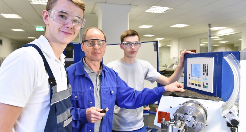
Unsurprisingly, computer numerical control (CNC) machine tools have become an essential part of our educational system. After all, a future in the ever-growing field of modern manufacturing depends on training programs in the classroom and hands-on experience with the latest educational CNC machines.
Whether learning to operate a versatile CNC milling machine, CNC router, or CNC lathe, becoming comfortable with user-friendly CAD/CAM software, or understanding G-Code and tool paths, CNC programs will prepare today’s high school students to become tomorrow’s CNC machinists.
CNC machines are a natural fit for the classroom, filling two critical roles: they are educational, introducing the next generation of high school or college students to the CNC technologies supporting today’s manufacturing and vocational, training CNC operators to fill the demand for CNC technicians in machine shops, fabrication facilities, woodshops, or wherever high-speed manufacturing and automation are changing the face of modern manufacturing.
However, decision-makers and leaders in vocational schools, high schools, secondary centers, and fab labs must determine which educational CNC machine tools make the most sense for their machining programs.
What Machines Should I Consider?
Three CNC machines correspond with the recent focus on STEM (Science, Technology, Engineering, and Mathematics): the CNC mill, lathe, and router. Although there are similarities among the three machine tools, they cover a broad area of operations, enabling them to offer a comprehensive real-world learning experience in CNC technology.
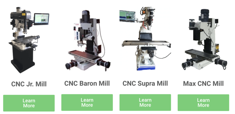
CNC Milling Machine
The advantages of learning to run a CNC milling machine are numerous. First, your students are learning to run a machine used in various industries, including aerospace, medical, and electronics. Aerospace allows them to machine components such as manifolds and landing gear parts. They could be helping to create prostheses, medical instruments, and medical devices in the future. Or they could be machining excellent electronic parts like amplifier housings.
CNC milling machines will keep your students safe as they learn. Many machines are enclosed, and operators are not required to be near the cutting tools, so flying chips and pieces of metal are not an issue.
Kids love technology, such as robotics, and CNC mills are equally exciting technology, with automatic tool changers, prototyping, or transforming a workpiece into a part. These machine tools’ speed, precision, and efficiency provide an adrenaline rush that turns CNC training into a fun-filled and meaningful experience.
Although students enjoy the technological aspects of CNC equipment, administrators will appreciate the affordability of quality CNC milling machines. For instance, CNC Masters, an American company based in California, manufactures versatile CNC vertical knee mills that are easy to learn and operate. Students will quickly build confidence in these rugged CNC milling machines capable of CNC and manual control (tutorials included) for under $15,000 brand new.
A CNC benchtop mill is the perfect solution for training centers with limited space. Although they have a smaller cutting area, benchtop mills feature a cast iron frame, robust power supply, and easy-to-learn control software ideal in an educational setting. CNC Masters offers budget-friendly “desktop” models starting at under $6,000.
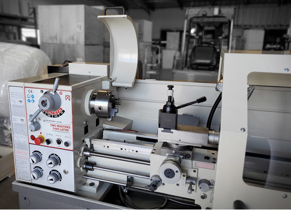
CNC Lathe
Although learning to operate and program CNC mills is a priority, a student’s education would be incomplete without thorough training on a CNC lathe. Like the milling machine, a CNC lathe operates from design instructions to produce precision machined parts. However, the CNC lathe takes a different approach to creating pieces since the workpiece is held in a chuck or collet and rotated by the main spindle as a fixed cutting tool removes material on various axes.
As a result, of this “turning” of the workpiece, CNC lathes produce precise cylindrical shapes with an outer diameter (OD) and an inner diameter (ID). Even though lathes are not as versatile as mills, they can machine many different parts and components for various industries, including medical, electronics, oil and gas, automotive, aerospace, mining, shipbuilding, power plants, and steel mills.
Students must learn to use a CNC lathe safely. Though the turning process is automated, special training is essential to help students develop the skills to comprehend the safety standards and programming parameters that ensure safe operation. As with the CNC mill, a CNC lathe operator is not required to be as close to the spinning chuck and flying chips as manual lathe operators; lathe safety should be a student’s priority.
High schools and vocational training centers should exercise caution when choosing a CNC lathe for their programs. Lightweight CNC lathes might have a lower purchase price, but they tend to get out of balance quickly, affecting the learning experience for would-be machinists.
Rugged CNC lathe machines, like those offered by CNC Masters, are designed for high-quality operation over long productions, meaning they will withstand the unintentional mistreatment that educational CNCs must endure. Plus, these lathes have an ease of use that allows students to experience advanced control even in the early stages of their training. And at a price starting under $11,000 and loaded with features, the CNC Masters lathes will make it easy to stay within your school’s budget.
CNC Router
CNC routers are designed for complex machining of softer materials such as wood, plastic, and aluminum. These machine tools are restricted to relatively thin materials, such as plywood boards or thin-gauge aluminum plates since the cutting tool has reduced motion along its Z-axis (up and down) compared to the CNC mill.
Closely aligned with the CNC milling machine, students who envision a future in woodworking will need to understand the intricacies of the CNC router, from its gantry-style construction, where the spindle travels along the X-axis (left and right) and the Y-axis (front and back), to its materials and Z-axis movement limitations, the CNC router contrasts with a CNC mill in many more areas than it compares to it.
What are the Best Educational CNC Machines?
Without intending to slight CNC routers, mastering the CNC milling machine and CNC lathe is the most promising path to a career in manufacturing. Vocational schools know there is a growing demand for well-trained CNC programmers and operators, and the ideal training method is to provide as much hands-on experience as possible.
The experts at CNC Masters strive to provide innovative technologies to high schools and vocational training programs by offering first-rate machine tools at affordable prices. Our CNC mills are excellent for metalworking and woodworking applications. Our lathes and desktop milling machines switch conveniently from CNC to manual mode, allowing students to learn both aspects of machining!


