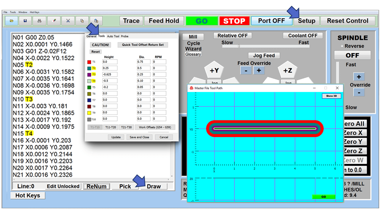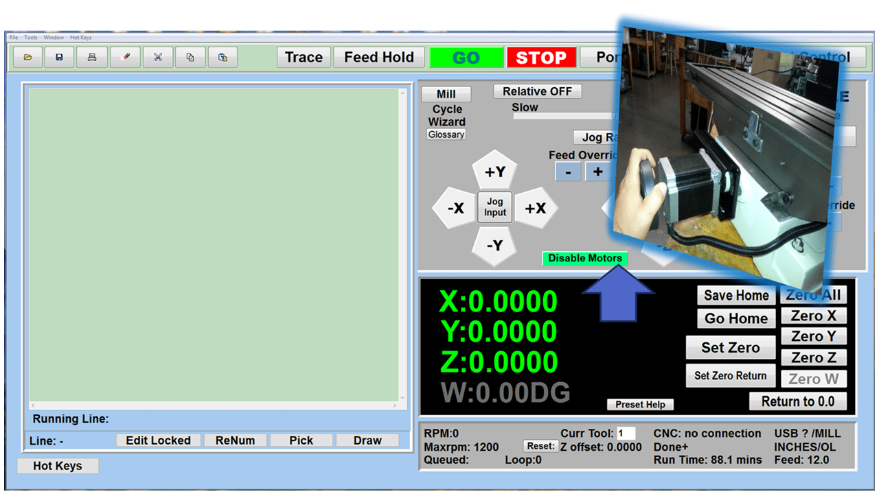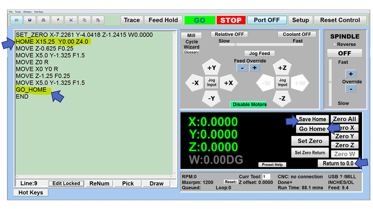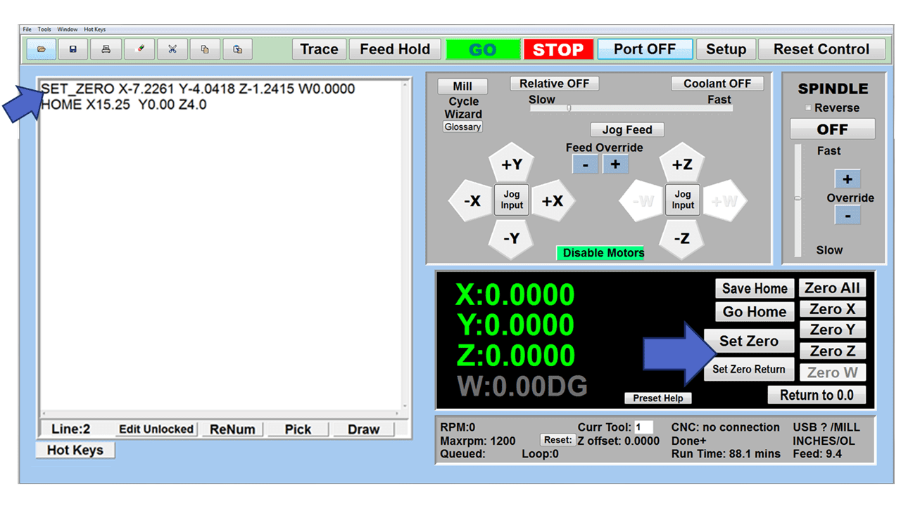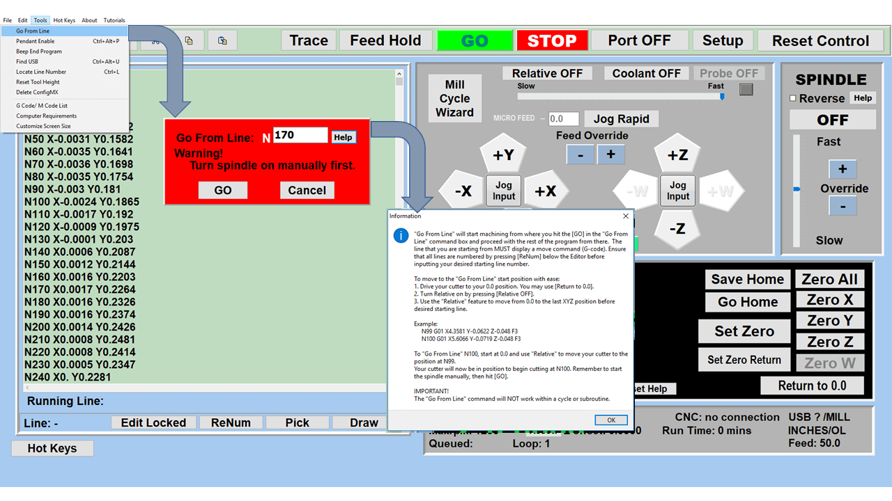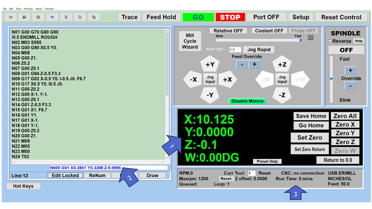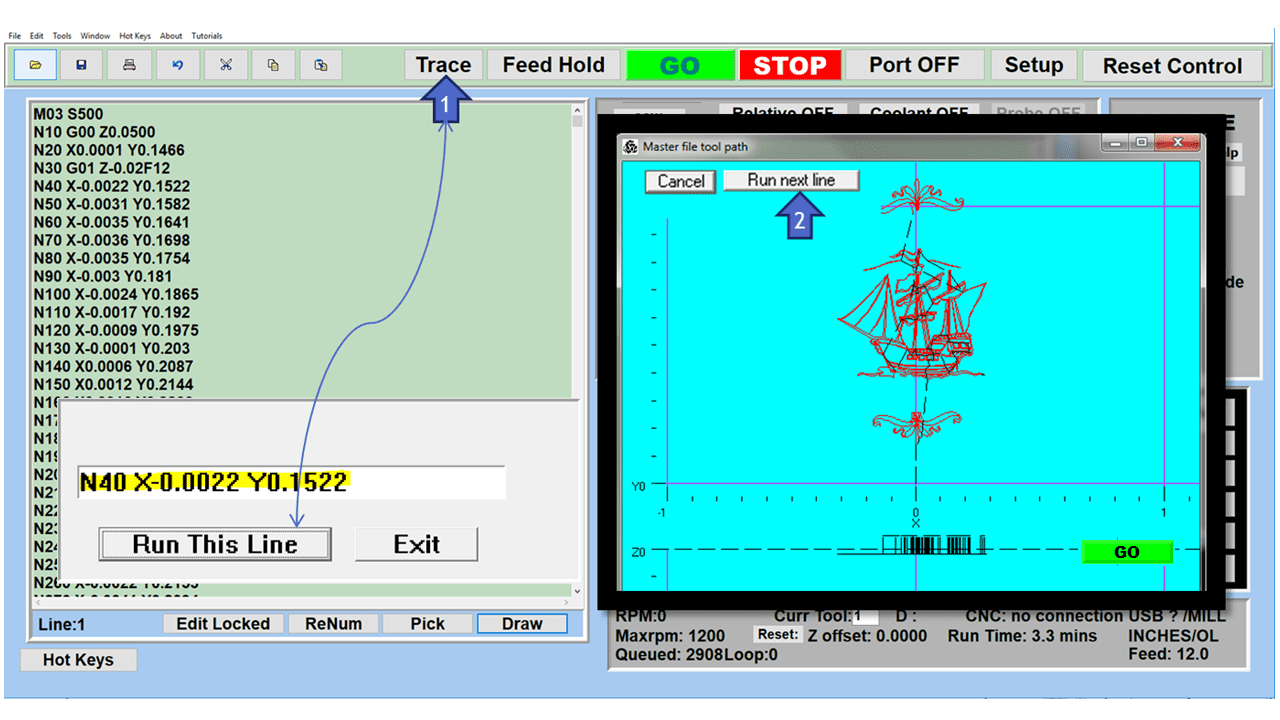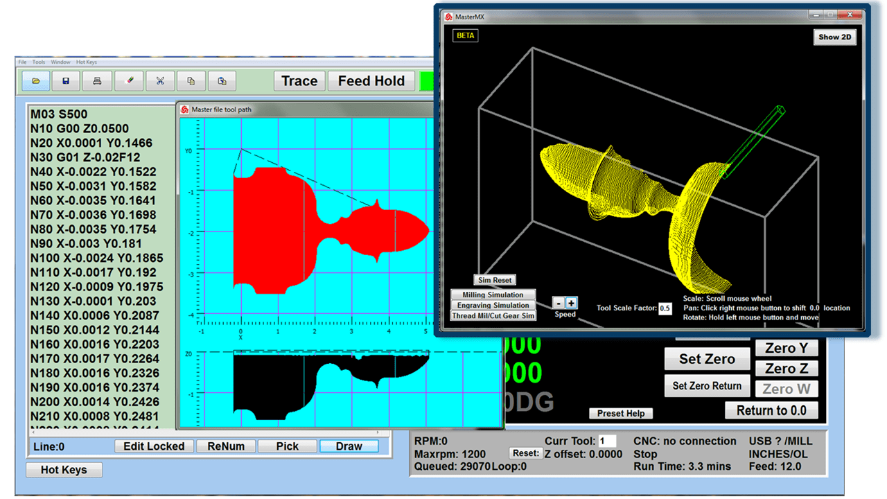
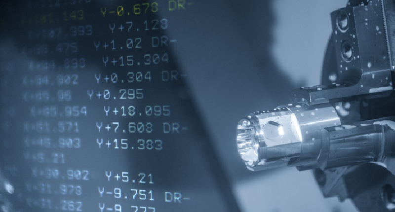
Like most coding languages, G-code looks strange when you first see it. There’s no apparent rhyme or reason, the numbers don’t seem to relate to each other, and the whole thing can appear a bit haphazard. It gets even stranger when you try to tell the codes themselves to the machines they work with. What do alphanumeric combinations have to do with x-y-z coordinate systems and toolpaths?
G-code programming is part of the firmware on all (or nearly all) machine tools. CNC mills, lathes, and 3D printers have a machine controller with native G-code language. While those languages can vary from manufacturer to manufacturer, they all follow the same general principles, and most codes stay the same.
What are G-Code commands?
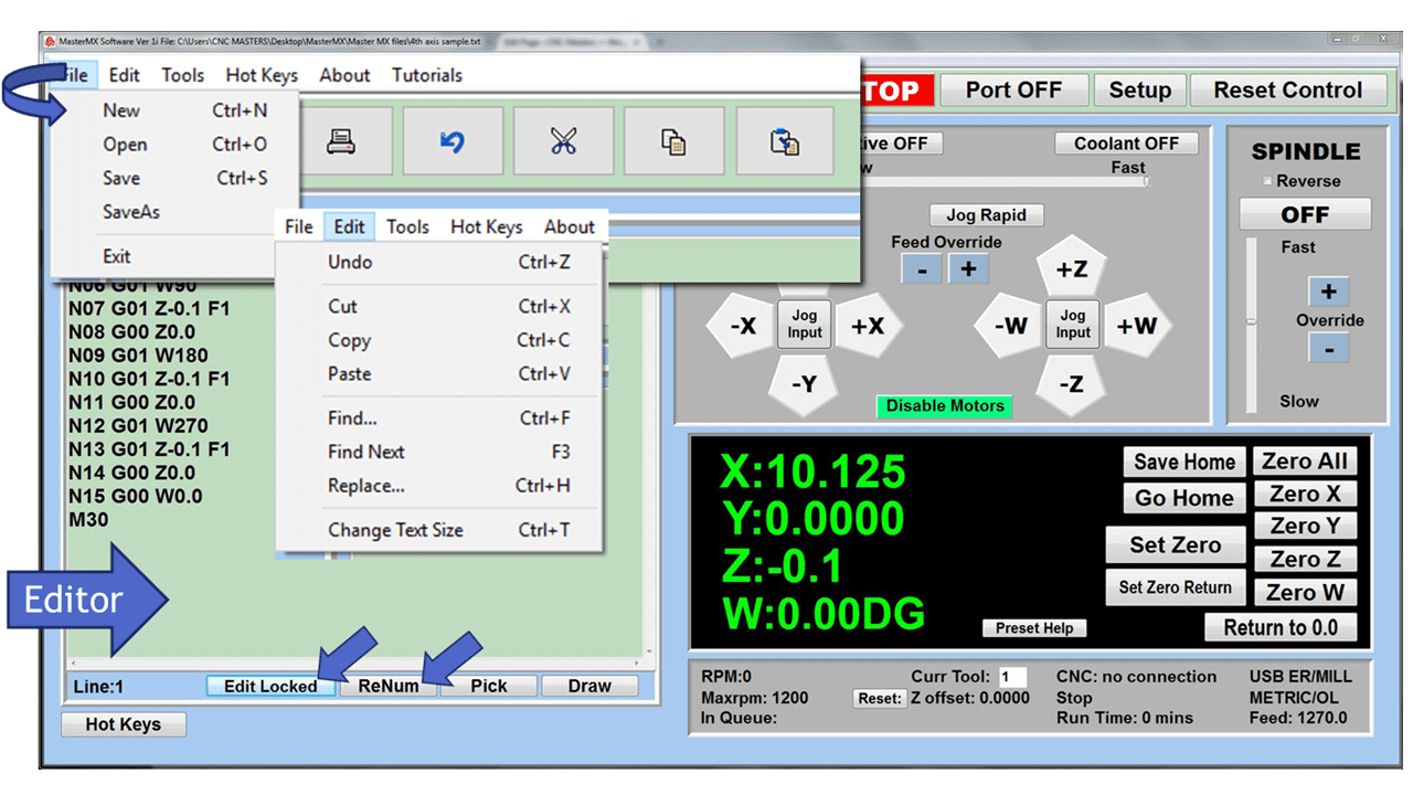
G-code is a complex but straightforward programming language that uses Cartesian coordinate systems to tell a machine tool where to go and what to do with the workpiece. Each command begins with an alphanumeric combo or code that starts with G or M. By stringing together lines of G-codes, operators can automate the entire machining process, identifying work coordinates to ensure precise cuts.
G-codes are more than “move here” and “cut this” commands. They include subprograms and subroutines (more on those later) and programs related directly to the machine itself. A lathe will have G-code commands to turn the spindle on and adjust the spindle speed, while a milling machine with multiple tools will specify the tool number and length for each operation. 3D printers will have their commands, like ones to heat the extruder to a designated temperature.
Individual G-code languages are typically available online and are open-source. Some, like the RepRap project for 3D printers, have been available for years with commands.
How many G-Code Commands are there?
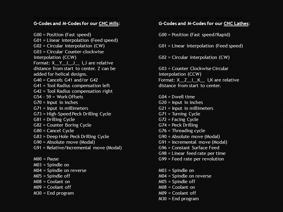
The complete G-code list runs to about a hundred commands, not including M-codes, subroutines, etc. For this article, we’ve selected 25 of the most valuable and common G-codes and M-codes for programmers, including some that may not be as familiar.
G-Code Commands
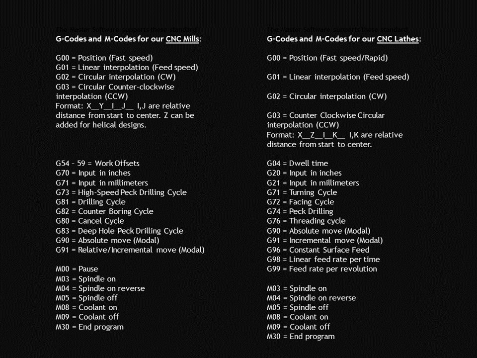
G20/G21 – Unit modes
Inches or millimeters? Use the G20 and G21 commands to select your unit of measurement. All size and location commands will be in inches with G20 and metric mode with G21. This setting must be set at the program’s beginning, or the machine could default to base settings or the previous program.
G00 – Rapid Travel
Often referred to as rapid traverse, G00 moves the CNC at the highest speed possible from its current position to its next one. Rapid moves can be placed anywhere in the program, especially at its start or end when it returns to the home position.
G01 – Linear Move
Otherwise known as linear interpolation, G01 sets the CNC movement mode to the straight-line movement (along the X-axis and Y-axis) using a feed rate specified by the feed (F) command. G01 is a modal command, meaning it will stay on until changed to another code in the same “movement” group of codes that include G00 (rapid travel) or G02 (clockwise circular interpolation).
G02/G03 – Circular interpolation (clockwise and counter-clockwise)
These G-codes move the CNC to a specific location along a specified arc or traveling clockwise (G02) and counterclockwise (G03). The movement’s speed is determined by the feed rate (F). When using the G02 and G03 commands, you must specify a start point, an end point, and a mid-point.
G17 – XY Plane Selection
Most movements in a CNC program are relative to the XY plane. Plane selection affects how G02, G03, cutter compensation and some canned cycles are handled.
G18 – XZ Plane Selection
Plane selection affects how G02, G03, cutter compensation and some canned cycles are handled. G18 tells the machine you are machining radii around the Y-axis.
G19 – YZ Plane Selection
Plane selection affects how G02, G03, cutter compensation and some canned cycles are handled. G19 tells the machine you are machining radii around the Z-axis.
G28 – Auto Home
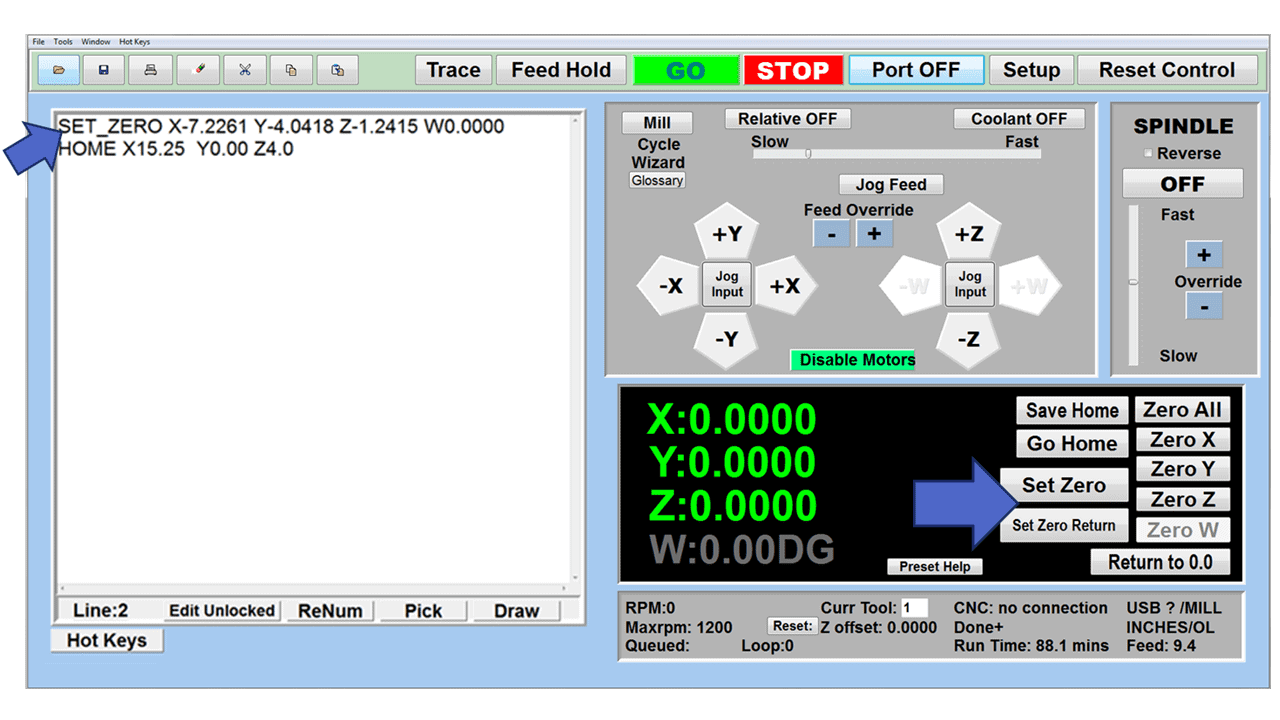
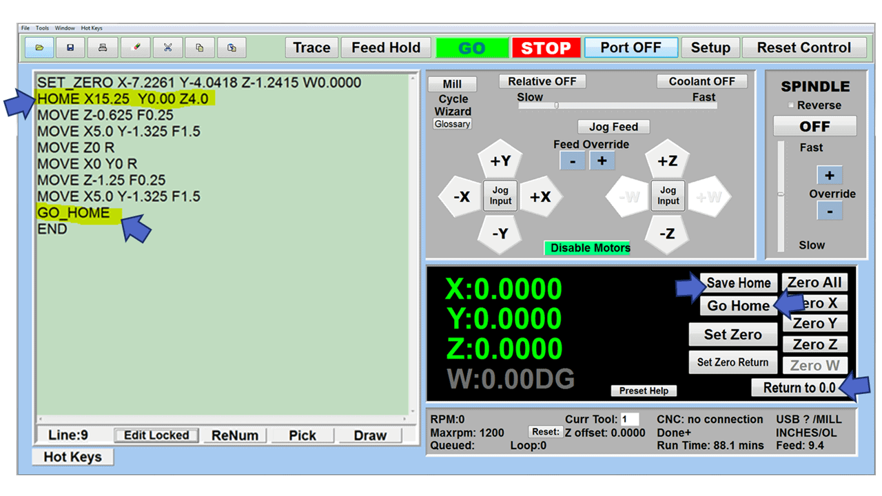
The G28 command sends the tool to its starting position. It’s useful both as a reset device and to set the limits and parameters of the cutting area. Operators can specify a midpoint in the G28 command to clear obstacles.
G40 – Cancel Cutter Compensation
Cutter compensation allows the CNC controller to adjust for the size of the cutting tool. Turning the cutter compensation on tells the machine to shift the cutting tool radius either to the left with G41 or right with G42. Setting the cutting tool’s diameter enables you to use the same program with multiple cutting tools. G40 turns off the cutter compensation modes G41 or G42.
G41 – Cutter Compensation Left
G42 – Cutter Compensation Right
G43 – Tool Length Compensation
The G43 command tells the CNC machine to turn on tool length compensation, and the H code (height) informs it of the amount to compensate. The H offset numbers are entered during setup and stored in the machine’s memory. They correspond to a value, the tool’s length, in a location called the offset table or library. Multiple H offsets can be stored in the tool table, each with a corresponding H offset value.
G49 – Tool Length Compensation Cancel
Turns off the tool length compensation initiated by the G43 command.
G54 thru G59 – Offset Codes
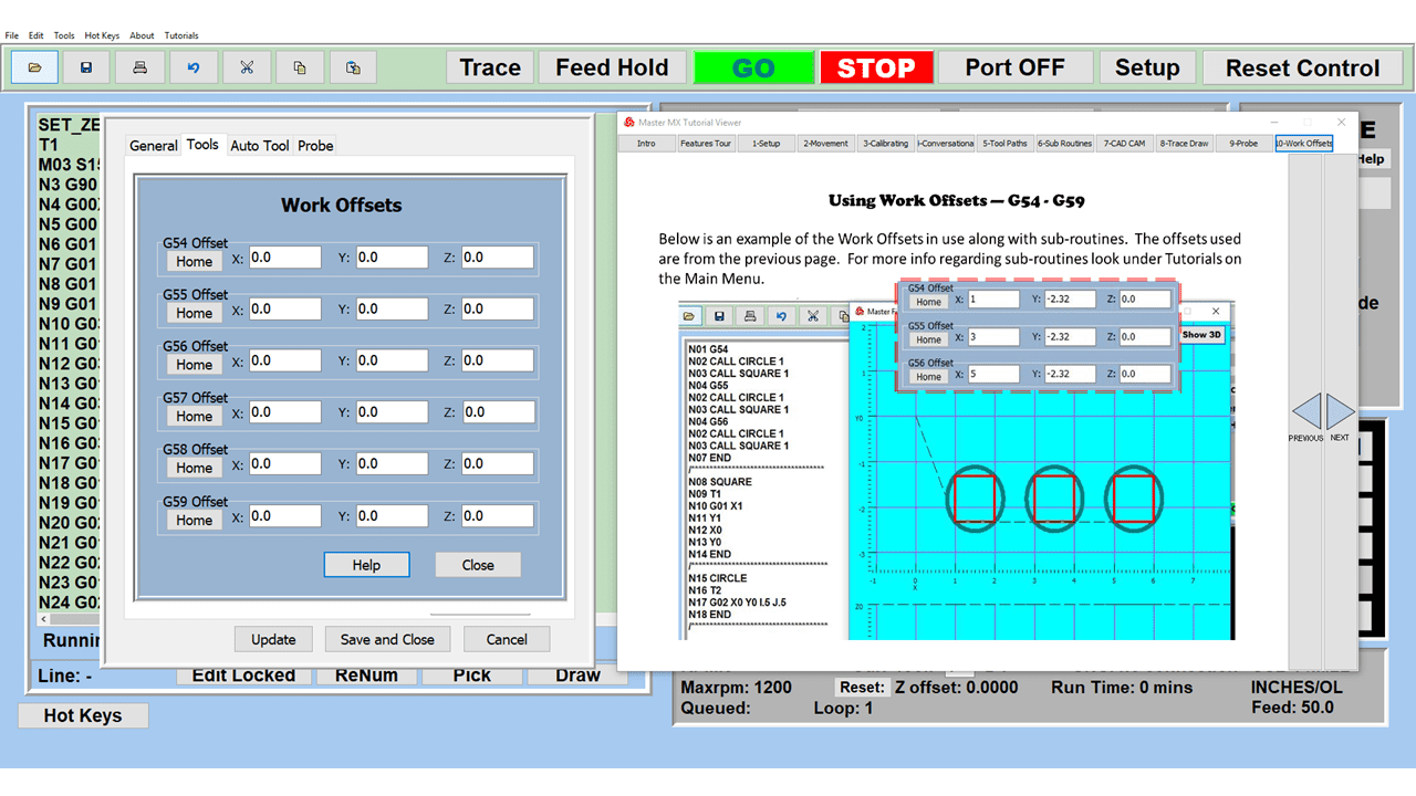
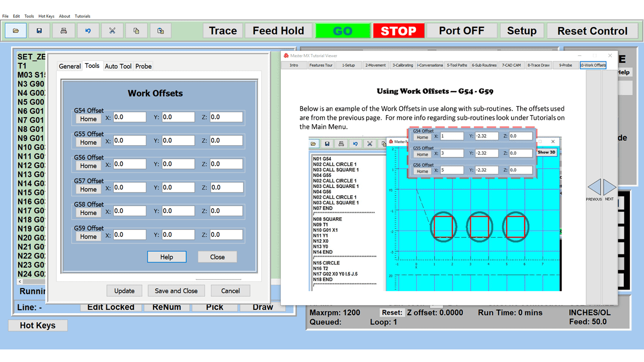
The G54 command tells the CNC machine where your part is located. In other words, it sets the work offset zero location currently used in the CNC program. Once the G54 work offset code is selected, all sizes and areas in the program will be relative to the new zero location of the part. Multiple work offsets can be set in a CNC, all relative to the machine’s zero location. This type of G code is called a modal command, meaning it remains in effect until it’s canceled. Think of work offsets like the presets on your radio, but you’re storing a location instead of a radio frequency.
Canned Cycles
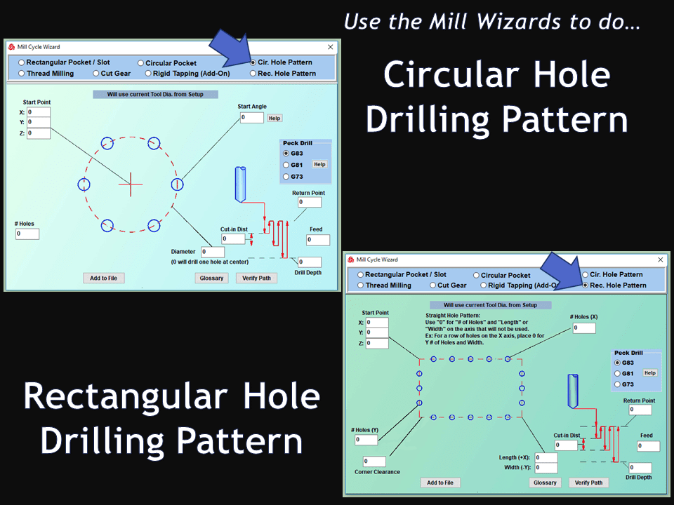
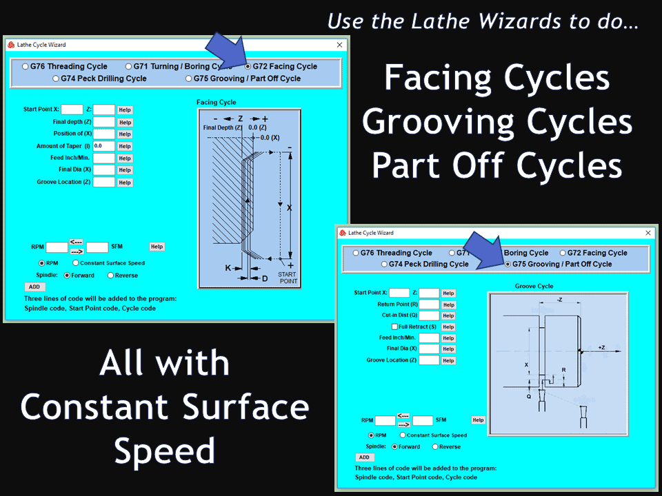
The following canned cycles are default mini-programs that speed up the programming process and allow programmers to add them to various program parts. They pertain to drilling, tapping, boring, and reaming along the Z-axis.
G73 – High Speed Peck Drilling
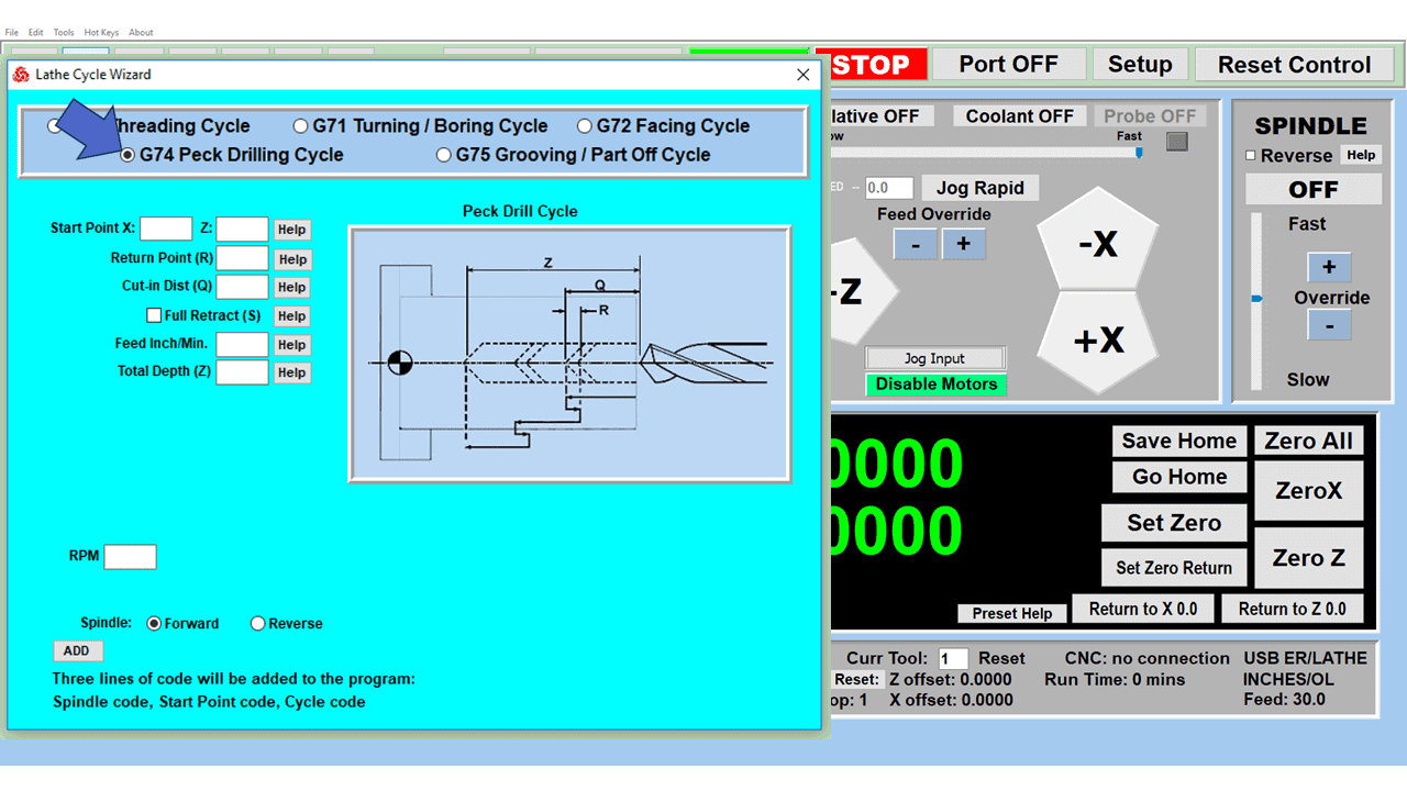
This cycle peck drills a hole by repeatedly drilling and retracting a small amount, then drilling deeper. It’s typically used as a chip breaker to prevent long chips that tend to wrap around the drill bit.
G74 – Left-Hand Tapping
This is a tapping cycle for left-hand threads where the spindle runs counter-clockwise. The machine feeds to the bottom of the hole, reverses the spindle direction, and backs out.
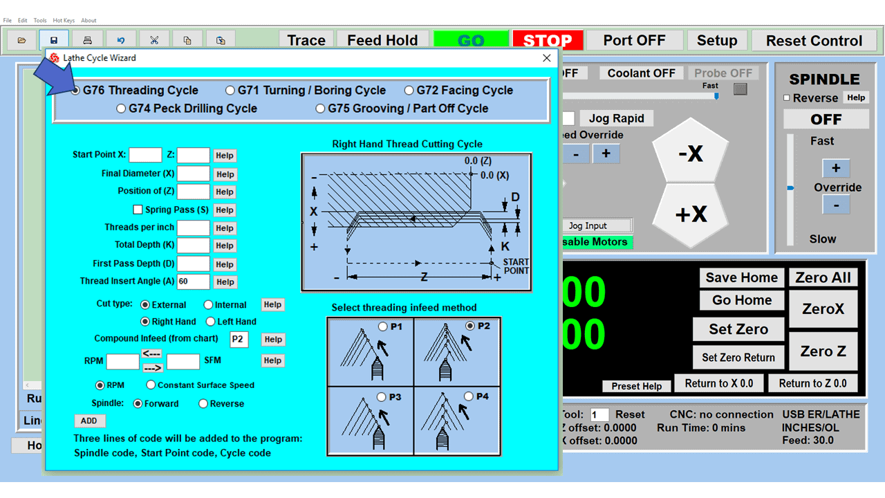
G76 – Fine Boring Canned Cycle
The machine bores a hole and stops the spindle. It then moves the tool away from the hole’s surface to prevent marking it and rapidly retracts the tool.
G80 – Canned Cycle Cancel
G80 cancels any active canned cycles for drilling, boring, tapping, and reaming.
G81 – Standard Drilling Cycle
This modal function allows the machine to drill the hole in one straight shot and then rapid retract the drill bit from the hole.
G82 – Standard Drill Cycle with Dwell
G82 drills a hole without pausing, dwells at the bottom for a specific time, and rapidly retracts out of the hole. G82 is typically used when the hole being drilled needs a better surface finish at the bottom of the hole.
G83 – Deep Hole Peck Drilling Cycle
The CNC machine drills in pecks while rapidly retracting entirely from the hole between each peck to help clear chips from the drill. Peck drilling is the first option for CNC programmers when making blind rather than thru holes. The pecking process breaks and removes chips, helping to prevent size and surface finish issues in the hole.
G84 – Right-Hand Tapping Cycle
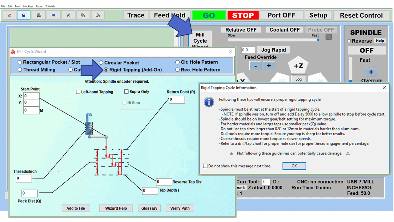
This is the standard tapping cycle with the spindle running clockwise. The CNC feeds the tap to the bottom of the hole and reverses the spindle direction to back it out.
G85 – Reaming Cycle
Much like the standard drilling cycle, the machine feeds to the bottom of the hole and then rapid retracts out.
G86 – Boring Cycle
The machine feeds to the bottom of the hole and then rapidly retracts. Unlike with the fine boring cycle, the tool is not pulled away from the surface which could leave a tool mark on the hole’s surface.
G87 – Back Boring Cycle
This operation bores a hole from the bottom to the top, which is the reverse direction of the G86 code.
G88 – Boring Cycle with Dwell
Bores a hole and then dwells at the bottom for a specified amount of time.
G89 – Back Boring Cycle with Dwell
The machine feed to the hole’s bottom, pause, and rapids out without pulling the tool away first.
G90 – Absolute Mode Positioning
Many G-code commands rely on the positioning. A G90 code sets the CNC to absolute positioning mode, meaning the CNC interprets all location values as relative to a single zero location, which is typically the workpiece zero location or CNC machine zero location (a.k.a. home position or reference point). Absolute positioning is the default, but it could pose a challenge under specific conditions.
G91 – Relative Positioning
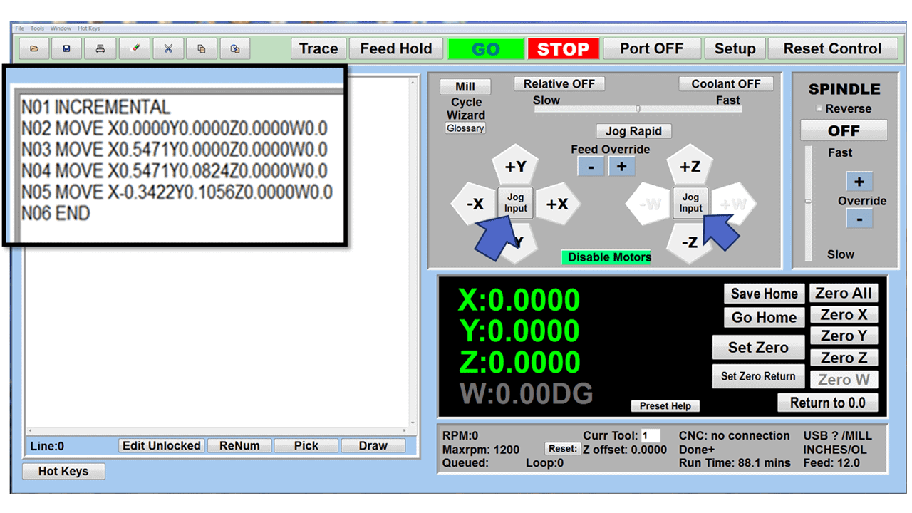
A G91 code sets the CNC to incremental positioning mode, meaning that the CNC will interpret all location values as relative to the position of the machine before making the move. The zero location of the machine changes each time the machine moves, which can be beneficial for repetitive work like drilling a series of holes. Specifying relative positioning cancels absolute positioning and vice versa.
G94 – Feed per Minute Mode
With G94, the feed rate is set to units (inches/mm) per minute. The tool moves at a set rate.
G95 – Feed per Revolution Mode
G95 sets the feed rate to units (mm/inches) per revolution, meaning the tool moves a designated rate for every spindle rotation.
G96 – Constant Surface Speed
The spindle speed varies to maintain the same surface speed of the material.
G97 – Constant Spindle Speed
The spindle operates at a constant RPM.
M-Code Commands
Most G-codes are standardized, at least for certain categories of machine tools. G-codes for milling machines should be broadly similar. The same goes for G-codes for lathes, 3D printers, and so forth.
M-codes are more complex. These are miscellaneous codes from the manufacturer, most of them varying from machine to machine, but there is a handful that stays consistent.
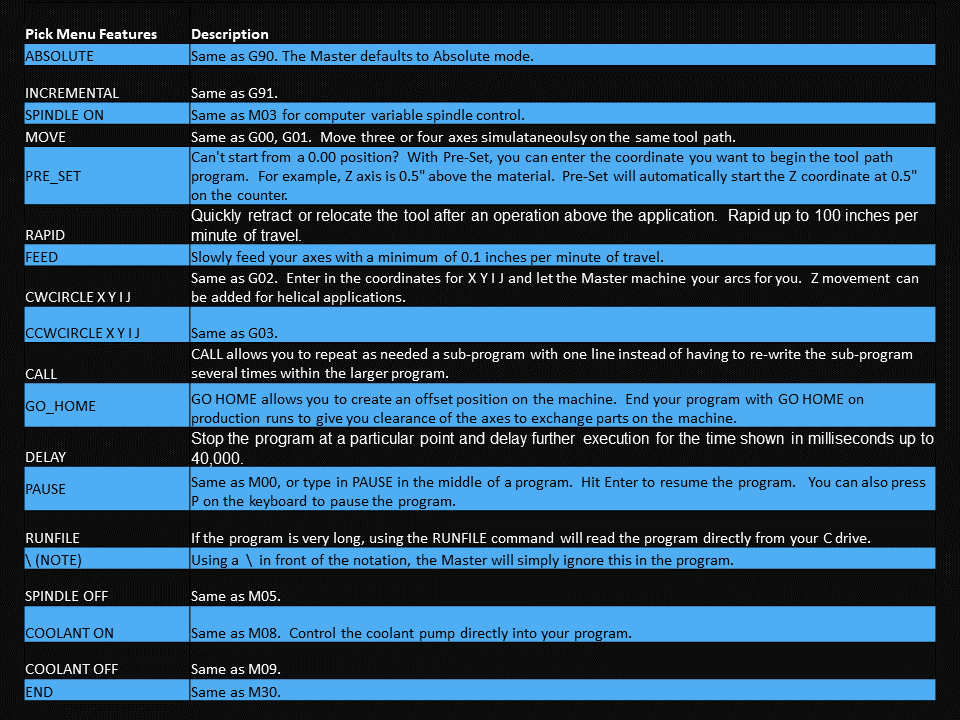
M00 – Program Stop
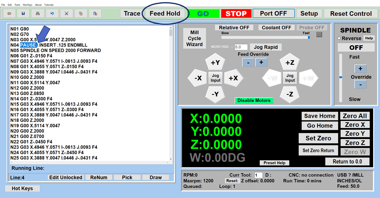
Want to run the program to a certain point and then stop it completely for an inspection? M00 is the command for you. It shuts down the current operation and the machine itself, allowing you to change tools, rotate the part, clean the machine – whatever you need to do.
M06 – Tool Change
Operators for CNC machines with automatic tool changers use the M06 command to switch tools within the program. For machines that require a manual tool change, the M06 command usually indicates to the machine that there’s a new tool at work.
M08 – Coolant On
The M08 code is a command used in CNC machines. It tells the machine to turn on the cooling system. This cooling system helps stop the machine and its tools from getting too hot. The M09 code, on the other hand, tells the machine to turn the cooling system off.
M01 – Optional Program Stop
If you might need to do a tool change, and you think you’d like a closer look at everything, then M01 is the right call. Insert an M01 command at regular intervals in your program to create potential checkpoints. Most CNC machines will have an optional stop button; press it, and the machine won’t shut down immediately. It will execute the program until it reaches the next M01 and then shut down.
M30 – Program reset/Return to start
M30 codes come in handy for continuous operation. They reset the program, telling the machine to go back to the beginning with the tool and start again.
A Code for All Seasons
Other codes exist, specifying spindle speed, setting incremental moves, and identifying or resetting the home position and end stop for the tool. Each code may influence the rest of the program, particularly with modal codes that remain active until a new code supersedes them.
Other codes control how fast different actions are performed, such as feed rates, constant surface speed, and cutter compensation. Still, others set the length of time for certain operations, down to milliseconds.
Despite being complex, a well-built G-code file contains everything the machine needs to conduct an operation without direct human intervention. 3D printing, 3D milling, and turning centers, and a huge range of other machine tools all rely on g-code commands.
You can find G-code programming tutorials online, from actual classes to informal YouTube training sessions. The specific G-codes mentioned above are standardized across machine tools, but you’ll need to look more closely at machine-specific lists to improve your skills.