CALL US TODAY

CALL US TODAY

woman operating a cnc lathe machine

Turning Centers vs Lathes: The Differences Explained

Lathe technology has existed for centuries, dating back to the Egyptians around 1300 BCE. Later, around 1550 CE, lathe machines produced wooden products in France. By the time of the 18th century Industrial Revolution, workers in England were using a modern version of the metal lathe.

Unlike milling machines, where the cutting tool rotates, and the workpieces move into it, the latheā€™s cutting tool is fixed and moves into a rotating workpiece, creating cylindrically-shaped parts. By definition, lathes have two axes: a Z-axis moving a cutting tool along the axis of the workpiece (toward the spindle) and an X-axis moving perpendicular to it (as in facing operations).

The original manual turning machines were integral to nearly every job shop, working side-by-side with milling machines and other machine tools in various manufacturing processes. And although two types of CNC lathes existā€”horizontal and vertical turning centersā€”we will focus on the horizontal variety in this article to avoid confusion since more people are familiar with them.

Letā€™s start with the basics:

What is a Lathe Machine Used For?

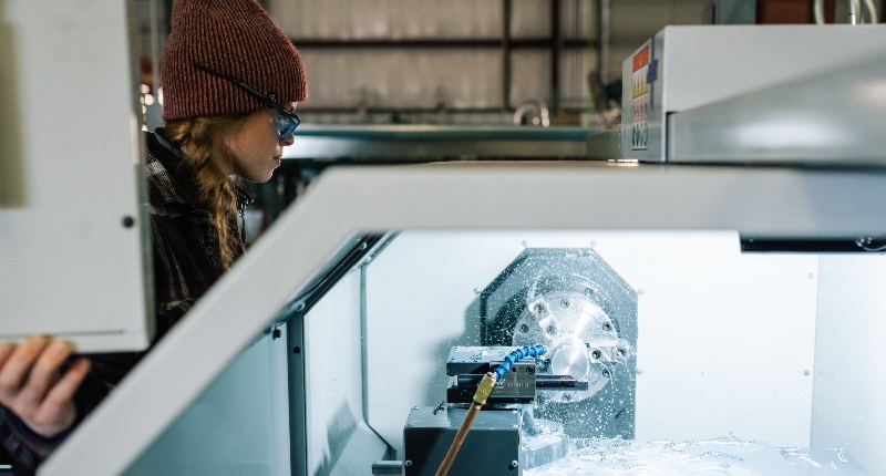
Today, there are few limits on what a lathe can produce. Most lathes are used for industrial purposes, with horizontal turning centers involved in high-production machining and small machine shops using a standard engine lathe to work on projects such as replacement parts for an older machine or vehicle.

Automation has relegated the two-axis lathe to a predominately supporting role since the advent of computer numerical control, or CNC machining, over the last fifty years. However, these manual versions are so versatile that they will likely never be entirely replaced by modern technology. And hobbyists and small enterprises will continue to find that manual lathes meet their needs and their budgets.

A traditional lathe machine

What are the Technical Differences between Lathes and Turning Centers?

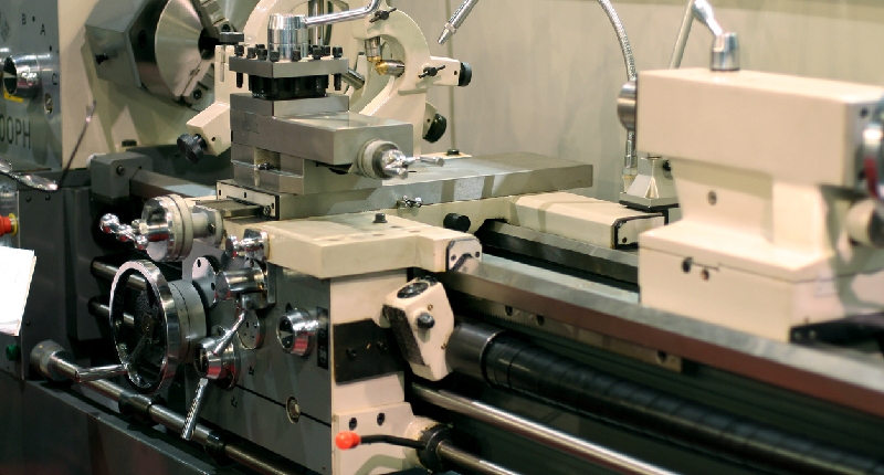
There is no hard and fast rule for making the distinction. Further muddying the waters is that CNC turning centers and lathes often look alike. Still, they usually refer to entirely different machines. Whether the lathe is a manual or CNC lathe, if it is capable of only two-axis (X and Z axes) machining, it is considered a lathe. The machine can perform operations including turning, facing, threading, knurling, drilling with the tailstock, boring, reaming, and taper turning. Still, each of these requires only the two axes and single spindles that are part of a lathe.

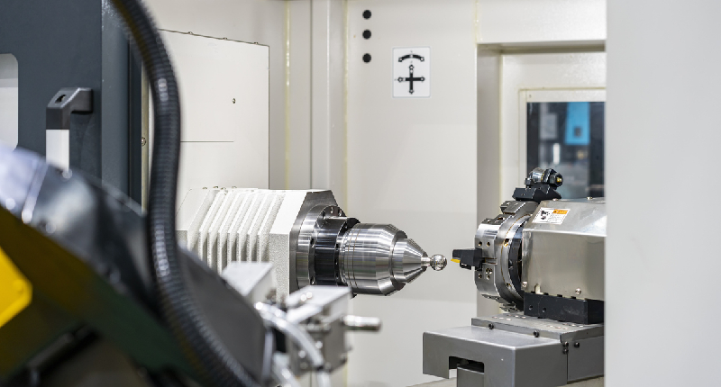
Lathes that include 3-axis, 4-axis, and 5-axis capabilities are known as turning centers, and they are an ā€œevolutionary leapā€ from the CNC and manual lathes of the past. While traditional lathes rotate a workpiece as a cutting tool removes material to create a round part, multi-axis turning centers are far more versatile in their cutting ability. Adding the extra axes and twin spindles allows turning centers to perform operations beyond a traditional latheā€™s capabilities.

Turning centers have cutting tool turrets for automated tool changing, live tooling, efficient chip removal, and a fully enclosed design for added safety and to keep high-speed coolant inside. Using sub-spindles for milling and drilling on multiple axes allows parts to be completed in one setup, eliminating the need to remove a workpiece for secondary operations on another machine.

A 4-axis turning center machining a piece of metal

Turning Centers Improve Conventional Lathe Operations

Even those operations that can be completed on a lathe are more efficient on a turning center. Turning centers drill, bore, and ream holes with ease as the workpiece spins, but with the live-tooling features, they can also perform this operation when the piece is stationary. The cutting tools drill and finish holes wherever the specifications require them.

Threading and taper cutting are time-consuming on a two-axis lathe, but they become quick and simple tasks with more than two axes. Turning center threading reduces machining time, and tapers can be applied anywhere along a workpieceā€™s length instead of only on its end.

What are the Advantages of Turning Centers?

A multi-axis turning center is particularly valuable for machining complex parts. Here are the four axes it employs:

  • X-axis: As mentioned, this is the normal lathe cutting axis, referring to the movement perpendicular to the axis of the stock, as in a facing operation using the cross-slide.
  • Z-axis: As the stationary cutting tool moves along the axis of the stock removing material, it travels along the Z-axis. Along with the X-axis, these are the two traditional lathe axes.
  • C-axis: The C-axis is movement around the axis of the stock, so it is the same axis as the spindle. However, during milling operations, the main spindle drive is disengaged, and a servo drive controls the C-axis, enabling accurate positioning. A C-axis allows slots to be machined into the part and holes drilled in the X-axis plane.
  • Y-axis: The Y-axis is moving perpendicular to the axis of the stock with a live tool or separate milling head. It works with the C-axis to mill slots and flats and drill holes off-center to the X and Z axes.Ā 

Some 4-axis CNC turning machines have turrets at both ends of the spindle, simultaneously allowing the machining of both ends of a workpiece. These models are helpful when machining long items such as axle shafts for the automotive sector.

Here are some benefits you can expect from 4-axis turning centers:

Versatile machining

Multi-axis turning machines allow turning operations and CNC milling capability on every workpiece surface. In other words, cutting slots, grooves, or designs on the front, back, top, and bottom with high precision is possible.Ā 

Complex design capability with speed

Combining a heavy-duty turning machine with CNC control and software enables intricate designs and configurations to be machined with shorter cycle times and higher accuracy. This benefit is essential for custom machining, rapid prototyping, and high-production work requiring a high-performance machine tool with multitasking capabilities.

Greater efficiency

Because multi-axis CNC machines act as turning centers and milling machines, companies can reduce the required machinery. For instance, there is no longer a need to cut round parts on a lathe and move them to a mill to add flats. The turning center completes all the operations on the same machine tool, increasing productivity, saving money, and minimizing waste.

Swiss Lathes: A Slight Variation on the Turning Center

The Swiss lathe is another type of CNC turning center capable of high production. They are based on the horizontal CNC turning center design described previously but add a few unique features. First, the headstock slides the material through a rotating collet as multiple tools engage the workpiece simultaneously, resulting in a ā€œbar feederā€ action for high production. Swiss Style CNC turning centers can mill, drill, turn, and tap, allowing them to produce parts accurately and quickly.

What is a Turning Center Used For?

Turning centers can produce parts for industrial use, including oil and gas, aerospace, automotive, construction, medical instruments, and military. Here are a few examples from different industries:

Aerospace

Turning centers play a significant role in producing parts for the aviation industry. Shafts, probes, eccentric hollow shafts, joint connectors, fasteners, landing gear parts, and structural components are just a handful of the items turning centers manufacture for the aerospace industry.

Automotive

The automotive industry needs parts and components in various shapes and sizes, and turning centers offer fast solutions to meet their demands. The machining includes gears, camshafts, transmission parts, steering components, hydraulic valves, valve housings, sensor housings, and clutches.

Electronics

Precision electronic parts must be produced with high consistency and reliability. Turning centers make earphone housings, computer panels, aluminum tubes for e-cigarettes, conductive pins, bushings, probes, and other electronic accessories.

Medical

Medical and dental instruments need CNC turning and machining processes to create packaging, processing machinery replacement and spare parts, R&D fixtures, analysis instrument parts, medical tooling, and medical mold components.

Mechanical

Parts used in the mechanical industry must meet specific technical specifications to ensure the quality of machinery or equipment. Some components include motor shafts, connector joints, shaft sleeves, hydraulic fittings, hose joint pipe couplers, and various fasteners.

How Much Do CNC Turning Centers Cost?

A standard CNC lathe typically starts at around $50,000. Add a Y-axis, and the price goes to almost $90,000, while a dual-spindle will set you back nearly $160,000. These are starting prices, and already they are beyond the budget of almost every independent shop owner or hobbyist. So, whatā€™s the alternative?

1440 CNC Lathe Machine
The 1440 CNC Lathe

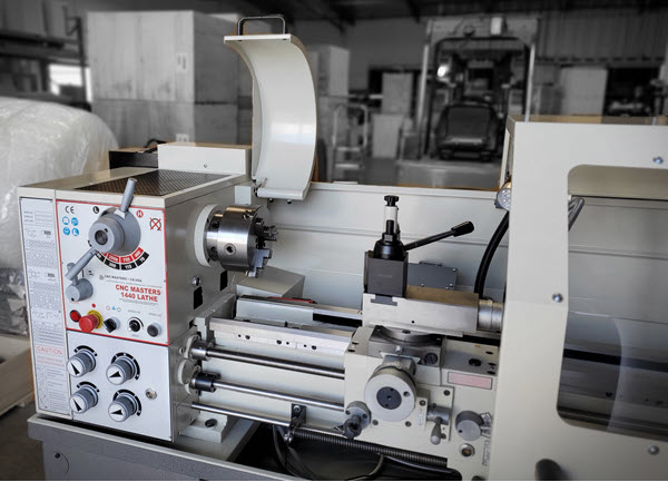
CNC Masters offers the CNC 1440 lathe machine, an elite CNC lathe machine that seamlessly converts back to all original manual modes for added flexibility. Designed with the independent shop owner in mind, the CNC 1440 delivers high-level performance with a smaller footprint and provides excellent value at under $15,000 fully loaded!

Designed to be reliable, portable, and compact, the 1440 CNC lathe and turning center open new opportunities for independent businesses. With a simple hands-on learning process, the machine tool is integrated to work efficiently with most CAD and CAM software programs. And these turning centers are built for fast and reliable automatic product development.

Break free of third-party CNC machining and turning centers, and keep the entire manufacturing process in-house. The CNC 1440 is one item in our broad-ranging product line made and serviced in the USA with an ironclad warranty to back them up.

Talk to the CNC experts at CNC Masters, and discover the benefits of this excellent and affordable turning center today!

About Peter Jacobs

Peter Jacobs is the Senior Director of Marketing at CNC Masters, a leading supplier of CNC mills, milling machines, and CNC lathes. He is actively involved in manufacturing processes and regularly contributes his insights for various blogs in CNC machining, 3D printing, rapid tooling, injection molding, metal casting, and manufacturing in general. You can connect with him on his LinkedIn.

Have Questions? Need a Quote?

Looking for more information about our CNC machines and services? Contact us today.

Contact

Slide 1

29. Create a Peck Drilling Program in Circular or Rectangular Patterns
Using the Circular or Rectangular Drilling Wizards, you can program the machine to drill an un-limited series of holes along the X and Y planes. Program it to drill straight through to your total depth, use a high-speed pecking cycle, or deep hole pecking cycle. You can program the cut-in depth and return point for a controlled peck drill application to maximize chip clearance.

Slide 1

20. Change up to 30 tools with compensation, and store your tool offsets for other programs
The MX supports…

Slide 1

21. Use the optional ATC rack up to 8 tools for milling, drilling, and rigid tapping applications
The CNC Masters Automatic Tool Changer Rack and Tools (US Patent 9,827,640B2) can be added to any CNC Masters Milling Machine built with the rigid tapping encoder option. The tutorial will guide you through the set-up procedure using the ATC tools.

Slide 1

22. Use the optional Rigid Tapping Wizard without the need for tapping head attachments
When you order your CNC Masters machine, have it built with the optional rigid tapping encoder. You can take any drill cycle program and replace the top line with a tapping code created by the wizard to tap your series of holes up to 1/2ā€ in diameter.

Slide 1

23. Use the optional Digital Probe to scan the profile and/or pockets of your fun/hobby type designs to write your tool path program and machine out a duplicate of your original design To ā€œsurfaceā€ scan an object, you can program the probe along the X or Y plane. The stylus will travel over the part starting on the left side front corner of the object and work its way to the end of the part on the right side. Depending on how the stylus moves, it will record linear and interpolated movements along the X, Y, and Z planes directly on the MX Editor.
To ā€œpocketā€ scan an object containing a closed pocket such as circles or squares, the scan will start from the top front, work its way inside of the pocket, and scan the entire perimeter of the pocket.
Under the Setup of the MX software you will find the Probe Tab which will allow you to calibrate and program your probe. Your ā€œProbe Stepā€, ā€œFeedā€, and ā€œData Filterā€ can also be changed on the fly while the probe is in the middle of scanning your object.

Slide 1

24. Use work offsets G54-G59 for nesting applications
The work offsets offer you a way to program up to six different machining locations. Itā€™s like having multiple 0.0 locations for different parts. This is very useful especially when using sub-routines/nesting applications.

Slide 1

25. Create a Rectangular Pocket / Slot with our selection of Wizards to help you build a tool path program
The Cycle Wizards for the mill or lathe makes it easy to create a simple tool path without needing to use a CAD and CAM software.
On this Wizard, the Rectangular Pocket / Slots, can be used to form a deep rectangular pocket into your material or machine a slot duplicating as many passes needed to its total depth.

Slide 1

26. Create a Circular Pocket Wizard
Input the total diameter, the step down, and total depth and the code will be generated.

Slide 1

27. Do Thread Milling using a single point cutter Wizard

Slide 1

28. Cut a gear out using the Cut Gear Wizard with the optional Fourth Axis

Slide 1

19. Disable the axis motors to manually hand crank each axis into place
Easily de-energize the axis motors by clicking [Disable Motors] to crank each axis by hand, and then press [Reset Control] to re-energize the axis motors.

Slide 1

30. The MX interface can easily be interchanged from Mill Mode to Lathe Mode
Use this interface for your CNC Masters Lathe. It contains all the same user-friendly features and functions that comes in Mill Mode. Simply go to the Setup page and change the interface.

Slide 1

31. Use Tool Change Compensation or the optional Auto Tool Changer Turret if your application requires more than one tool in a single program
You can offset the length and angle of each tool and record it under Tools in your Setup. The program will automatically pause the latheā€™s movement and spindle allowing you to change out your tool, or allowing the optional ATC Turret to quickly turn to its next tool and continue machining.
On the MX interface, you also have four Tool Position buttons. Select your desired T position, and the auto tool post will quickly turn and lock itself to that position.

Slide 1

32. Use the Lathe Wizard Threading Cycle to help you program your latheā€™s internal or external threads in inches or metric

Slide 1

33. Use the Lathe Wizard Turning / Boring Cycle to help you program simple turning and boring cycles without having to go through a CAM or writing a long program with multiple passes

Slide 1

34. Use the Lathe Wizard Peck Drilling Cycle to help you program your drill applications or for face grooving

Slide 1

35. Facing / Grooving / Part Off Cycle Wizards ā€“ with Constant Surface Speed
These cycles can be used with Constant Surface Speed allowing the spindle speed to increase automatically as the diameter of the part decreases giving your application a consistent workpiece finish. With CSS built into the wizard, there is no need to break down the cycle into multiple paths and multiple spindle speed changes.

Slide 1

36. This is our list of supported G and M codes which can be found under Tools > G Code/ M Code List in the MX
If you plan to use a third-party CAM software to generate your tool path program, use a generic FANUC post processor and edit it to match our list of codes. As an option, we also sell Visual mill/turn CAM software which comes with a guaranteed post processor for our machines to easily generate your tool path programs based on your CAD drawings.

Slide 1

37. Our pledge to you…

Slide 1

10. Run each tool path independently to study its movement
1. Run the machine on Trace mode. You can run each tool path independently, one line at a time to study the tool path movement on the machine to verify the position of the application and if any fixture/vise is in the way of the cutterā€™s path.

2. You can also verify your program by clicking on the Trace and Draw buttons together. This will allow you to view each tool path independently one line at a time in the Draw Window.

Slide 1

2. Clutter Free Interface
The MX is engineered for the CNC MASTERS machine so you do not have to fiddle with a detailed complicated configuration that can be overwhelming. Just load in the MX and start machining!2. Clutter Free Interface
The MX is engineered for the CNC MASTERS machine so you do not have to fiddle with a detailed complicated configuration that can be overwhelming. Just load in the MX and start machining!

Slide 1

3. Features Tour and Tutorials Included
The Features Tour will give you a quick run-down on all the features the MX can do for you. The Tutorials are easy to follow even for the first time CNC machinist.
Feel free to download the MX on any of your computers. We recommend downloading the MX along with your CAD and CAM software there at the comfort of your office computer to generate your tool path programs. You donā€™t need to be hooked up to the machine either to test your program in simulation mode.

Slide 1

4. Navigate and Edit Your Program through the MX interface with Ease
With a few clicks of the mouse or using touch screen technology, you can easily navigate through the MX interface importing saved programs into the Editor from the File drop down menu. Using standard windows features to edit your program you can then lock the Editor Screen to avoid accidental editing, and if you need to insert a line in the middle of a program, just click on [ReNum] to re-number your tool path list.
You can create a program or import CAM generated G-code tool paths into the Editor
The X Y and Z W arrow jog buttons are displayed from the point of view of the cutter to avoid confusion when the table and saddle are moving. You can also adjust your spindle speed and coolant control while jogging each axis.

Slide 1

5. Feed Hold ā€“ Pause in the Middle of your Program
Feed Hold lets you pause in the middle of a program. From there you can step through your program one line at time while opting to shut the spindle off and then resume your program.
You can also write PAUSE in the middle of your program and jog each axis independently while your program is in pause mode.

Slide 1

6. Hot Keys
Hot Keys is an alternative method to easily control your machine using your hard or touch screen keyboard. One can press P to pause a program, press S to turn Spindle On, G to run a program, Space Bar to Stop, J to record your individual movements one line at a time to create a program in teach mode.

Slide 1

7. Pick Menu ā€“ for conversational mode programming
Write FANUC style G-codes directly into the Editor or select commands off the [Pick] menu and write your tool path program in conversational mode such as what is written in the Editor box. You can even mix between conversation commands and G-codes in the same program.

Slide 1

8. Pick Menu List of Options
Use commands such as MOVE, SPINDLE ON/OFF, COOLANT ON/OFF, PAUSE, DELAY, GO HOMEā€¦. to write your tool path programs in conversational mode.

Slide 1

9. Draw the Tool Path to verify it before pressing Go
Hit Draw to view your tool path program drawing, check out its run time, or even simulate the tool path in 3D mode. This can be helpful to quickly verify your program before running it. You can also slow down or speed up the drawing or simulation process.
You can also hit Go within the Draw Window itself to verify the cutterā€™s position on the machine. The current tool path will be highlighted and simultaneously draw out the next path so you can verify what the cutter will be doing next on the program.

Slide 1

MX Software ā€“ Easy to Use, Easy to Learn ā€“ Included with your machine purchase
The MX software is designed to work seamlessly with your CNC Masters machine. It is made to work with Windows PC ā€“ desktop, laptop, or an all in one ā€“ on standard USB. Use it on Windows 8 or 10 64-bit operating systems.
No internal conversion printer/serial port to USB software or additional conversion hardware is used with the MX.

Slide 1

11. Counters display in Inches or Millimeters ā€“ Continuous Feed
1. When running a program, the counters will display a ā€œreal-timeā€ readout while the machine is in CNC operation without counting ahead of the movement.
2. The current tool path is highlighted while the machine is in operation without causing slight interruptions/pauses as the software feeds the tool path to the machine. The MX internally interprets a program ten lines ahead to allow for ā€œcontinuous machiningā€ avoiding slight interruptions as the machine waits for its next tool path command.
3. ā€œRun Timeā€ tells you how long it takes to run your tool path program.

Slide 1

12. Use the ā€œGo From Lineā€ command to start in the middle of your program
If you ever need to begin your program from somewhere in the middle of it, use [Go From Line] which you can find under Tools. The Help guide will walk you through how to position the cutter without losing its position on the machine.

Slide 1

13. Exact Motion Distance without over-stepping on an axis while jogging
Use ā€œRelative ONā€ to enter a specific coordinate to jog any of your axes to an exact location without having to write a program. Itā€™s like using ā€œpower feedā€ but easier. You can jog an exact distance on any of the axes without needing to keep the key pressed down and mistakenly over-step the movement releasing your finger too slowly off the jog button.
Letā€™s say you need to drill a hole exactly 0.525ā€ using the Z. So you enter 0.525 in the Z box. Next, adjust the JOG FEED RATE slider for the desired feed rate. Then ā€œclick onceā€ on the +Z or -Z button to activate the travel. In this case you click once the -Z button first to drill the hole exactly 0.525ā€. Then click once on the +Z button to drive the axis back up 0.525ā€.

Slide 1

14. Teach Mode ā€“ Jog Input
You can create a tool path program by storing each point-to-point movement by simply jogging an axis one at a time. Click on either of the Jog Input buttons to store each movement on the Editor Screen. You can then add Spindle ON, feed commands, and press GO to run the new program as needed. This is a great feature to help you learn to create a program by the movements you make on the machine without necessarily writing out an entire program first.

Slide 1

15. Override on the fly to adjust the Jog Feed to Rapid or the Spindle Speed during the middle of a program
1. Jog Feed and Rapid with Override: You can adjust feeds using the slider from slow minimum 0.1ā€³ per minute to a rapid of 100ā€³ per minute of travel. You can even micro-step your jog as low as 0.01ā€/min. The [-][+] buttons allow you to fine tune feeds in 5% increments while the program is in motion.
2. Spindle Speed with Override: You can adjust speeds using the slider from a slow minimum RPM to the max RPM according to the machine setup. The [-][+] buttons allow you to fine tune feeds in 5% increments while the program is in motion.

Slide 1

16. Adjust Counters using Pre-Set if you cannot begin the program from 0.00
In a situation where you cannot begin your cutter at itā€™s 0.00 location, you can ā€œPre-Setā€ directly into the counters by typing in your beginning coordinate. You can press Go from here to run your program. You can also ā€œzero allā€ or ā€œzeroā€ your counters independently. With one click of the [Return to 0.0] button, all axes will travel back to its respective 0.0 on the machine.

Slide 1

17. Set and Save your 0.00 position for future runs
Set and save your 0.00 position on the machine. These coordinates will be recorded as the first line of the program in the Editor Screen. Should you desire to return to this program at a later date, you only have to click on the Set Zero Return button. This will command the machine to automatically jog each axis to its saved ā€œsetā€ 0.00 position according to the recorded coordinates at the first line of the program.

Slide 1

18. Create a ā€œHomeā€ position to clear your application and run multiple times
Letā€™s say you need to machine one application times 100 pieces. This usually requires a jig to retain that physical 0.00 position. But in this case, you want the program to end with a clearance of the axes to easily switch out the next piece of stock and start again. With Save Home, you have the ability to save this offset (home) position while still retaining your Set Zero position where the machine will mill your part out. Pressing [Save Home] will record this new position under the Set Zero line in your program.
Pressing [Go Home] will jog your axes back to your ā€œsaved homeā€ position where you originally pressed the Save Home command. You can also input GO_HOME from the Pick Menu as its own tool path in your program. At the completion of your program the axes will end at your Home position. Replace your part, then press [Return to 0.0] button to allow the axes to return to its zero position, and press Go to start your next run.

previous arrow
next arrow