CALL US TODAY

CALL US TODAY

A three-jaw chuck attached to a rotary table ensures secure workholding

Guide To Selecting the Best Rotary Table for Your Milling Machine

What does a rotary table do?
How do rotary tables work?
What are the advantages of a rotary table for a milling machine?
What is the difference between a rotary table and a dividing head?
What should a buyer consider when purchasing a new rotary table?
A rotary table is worth the investment

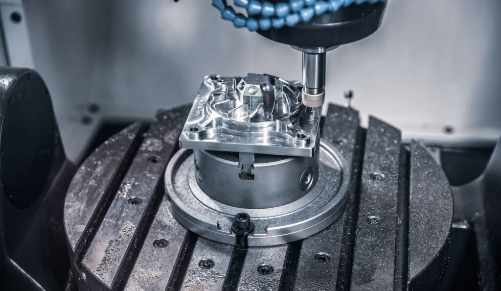
Rotary tables can be an integral component of milling machines because they add significantly to the machines’ versatility and precision. Often seen as a fourth axis, they are attached to the machine’s worktable and provide the capability to cut workpieces along multiple axes. They can rotate workpieces at various speeds, accommodating a wide range of milling tasks and enabling intricate, complex designs to be machined.

Adding a rotary table to a milling machine provides several advantages to your machinists. Having another axis to work with gives milling machine users more precision and accuracy without changing part positions.

Also, an additional axis makes any milling machine more versatile. As a lathe machine enables the creation of cylindrical-shaped parts, a rotary table provides some of the same benefits. It offers more precision to a complex design, reducing time and costs for producing specific components.

Understanding the functionality and advantages of rotary tables is crucial for anyone involved in the metalworking or woodworking fields. These devices offer superior precision in milling operations and allow for efficient mass production, making them an indispensable tool in any machining setup. This article explores the intricacies of rotary tables on milling machines ā€“ and highlights their operation, benefits, and pivotal role in the broader manufacturing context.

What does a rotary table do?

A rotary table can be an invaluable asset in the milling process, offering a multitude of uses that enhance accuracy, versatility, and efficiency. It enables precise machining of complex parts by rotating the workpiece at fixed intervals to machine multiple sides without manually repositioning the piece, ensuring precision and uniformity.

Operates horizontally and vertically

Part of the rotary table’s versatility lies in its capacity to be used horizontally and vertically, paving the way for various applications in various fields. When used horizontally, it offers a stable platform for machining radii and angles, while the vertical rotary table can be used with an indexing plate for precise machining of gears or to drill bolt hole circles around the circumference of a component or part. This dual horizontal & vertical orientation usage not only maximizes space, but also enhances productivity and creativity.

Allows for creation of larger parts

Also, the milling rotary table permits the creation of larger parts that would otherwise be impossible to produce on a standard milling machine. Through indexing, machinists can cut large-diameter components such as oversized wheels and gears with unparalleled precision. Using the rotary table in a horizontal orientation even allows machining large diameters on smaller machine tools.

Machines complex and intricate parts more easily

In addition to machining complex parts, the rotary table can create intricate patterns made possible by moving the table at precise angles or increments. For example, creating gear teeth requires precise, angular cuts, accomplished easily with a rotary table.

Creates accurate circular features

Furthermore, the rotary table can drill equidistant holes on a circular path. This operation, otherwise difficult to accomplish, is done smoothly with the help of a rotary table, which accurately positions the workpiece for the drilling operation.

Rotating the workpiece against a cutting tool allows shops to use it to cut perfect arcs and circles. This capability proves particularly useful in industries such as automobile and aerospace, where parts often require accurate circular features.

Additionally, the use of a rotary table in milling extends to the creation of spiral features. By coordinating the movements of the milling machine and the rotary table, companies can produce spiral features such as the threads of a screw.

A precision rotary table on a milling machine serves as a versatile tool that enhances the capabilities of the milling process. It provides the means to machine complex pieces, large parts, intricate patterns, equidistant holes, arcs, circles, and helical features with precision, thereby broadening the scope of possible applications of a manual or CNC milling machine.

How do rotary tables work?

Many rotary tables are manually operated, although tables under the control of CNC machines also offer a fourth axis to CNC mills. Rotary tables have a heavy-duty base that allows clamping onto another table or fixture. The table on which the workpiece is clamped is precision machined, and T-slots are typically provided for workholding purposes.

Rotary tables are typically mounted flat, meaning the table rotates around a vertical axis. It can also be positioned on its end to rotate about a horizontal axis.

A through hole, machined in the table’s center, allows for a Morse taper arbor, center, or fixture. Many models can accommodate a 3-jaw chuck for even more convenient part holding. The table rotates freely to enable indexing, and a worm or handwheel controls it. High-precision tables come with duplex worms to compensate for backlash.

What are the advantages of a rotary table for a milling machine?

Rotary tables on milling machines offer a multitude of benefits:

  1. Versatility: They allow for a wider array of machining operations, including drilling holes at equal intervals, cutting complex curves, or machining irregular shapes.
  2. Precision: Rotary tables provide the ability to work with a high degree of precision and repeatability, ensuring high quality of the final product.
  3. Flexibility: They can be used both vertically and horizontally, providing flexibility in completing different types of jobs.
  4. Time-Efficiency: By automating the rotation of the workpiece, they save time and potentially reduce operator errors.
  5. Cost-Effectiveness: Despite the initial investment, the enhanced capabilities and time efficiencies can lead to overall cost savings in the long run.

What is the difference between a rotary table and a dividing head?

A rotary table and a dividing head serve different purposes. A rotary table allows the operator to rotate the workpiece around a vertical or horizontal axis. This feature is handy for milling radial arcs and complex, multi-angle, precision work.

On the other hand, a dividing head, also known as a spiral head, is more specialized. It allows a workpiece to be rotated to any specified angle and divided into equal parts for tasks like gear cutting, creating flutes in twist drills, or cutting helical paths. While both devices provide rotational capabilities, the dividing head offers more precision and versatility for complex tasks.

What should a buyer consider when purchasing a new rotary table?

Here are a few considerations as you shop for a rotary table:

Put a three-jaw chuck at the top your purchasing ā€œwish listā€

Similar to a lathe chuck, a three-jaw chuck is an essential component of a rotary table because it securely holds and rotates the workpiece. The three jaws, evenly spaced 120 degrees apart, move simultaneously and radially inward or outward. Turning the chuck key actuates a scroll plate, which drives the jaws. As the jaws converge towards the center, they grip the workpiece.

Invest in a tilting rotary table

Investing in an adjustable tilting rotary table for your milling machine can significantly amplify its versatility, improving productivity and efficiency. The tilting feature enables the operator to mill at various angles without repositioning the workpiece, which can be particularly beneficial for complex multi-angle machining tasks. Moreover, a tilting rotary table can enhance precision and save time by providing the capacity to hold the workpiece in place during machining. It’s an invaluable tool for streamlining operations and maximizing the potential of your milling machine.

Purchase a tailstock for machining long pieces

Although you won’t need a tailstock for every job, it is necessary when machining long, thin pieces with the rotary table in a vertical position. It can help prevent these parts from vibrating during machining, and it secures parts to prevent dislodging.

Include a set of dividing plates

Dividing plates, in conjunction with a rotary table, enable accurate rotation of a workpiece to specific angular positions. Machinists can create various shapes, gears, or objects with angular features by using two dividing plates capable of up to 100 positions.

Chose a low-profile model

A low-profile rotary table provides several distinct advantages in precision machining applications. Its slim design minimizes the distance between the workpiece and the table surface, reducing the potential for deflection, vibration, and inaccuracies during machining. The low profile design allows for greater workpiece clearance, allowing larger parts or complex setups. Also, low-profile rotary tables are often lighter and more compact, making them ideal for use in space-constrained environments.

Check the tableā€™s gear ratio

The gear ratio of a rotary table is critical as it directly influences the table’s speed and torque. A higher gear ratio implies that the table will rotate slower but with greater torque, making it ideal for tasks requiring significant force. Conversely, a lower gear ratio means the table will rotate faster but with less torque, suitable for functions that value speed over power. For example, a 1:90 gear ratio means one handle rotation turns the table four degrees.

Buy your rotary table from a reputable manufacturer

Several manufacturers produce excellent rotary tables. For example, CNC Masters, Vertex, and Vevor have earned reputations for reliability, reasonable price tags, and decent warranties. CNC Masters offers a great 4th axis rotary table. It features a 6″ diameter table, three T-slots to secure a front mount jaw, a Morse taper center sleeve size #2 to secure a jaw with a Morse taper center shaft, and itā€™s 4″ from the center sleeve to the base of the rotary table.

A rotary table is worth the investment

Depending on your work type, a rotary table can be an indispensable component of the milling machine because it provides the capability to achieve precise and complex machining tasks. Their ability to rotate workpieces at various angles and indices ensures high accuracy and efficiency, enhancing the versatility of milling operations. Therefore, investing in a high-quality rotary table is a prudent decision that will significantly increase the performance and productivity of your milling operations.

About Peter Jacobs

Peter Jacobs is the Senior Director of Marketing at CNC Masters, a leading supplier of CNC mills, milling machines, and CNC lathes. He is actively involved in manufacturing processes and regularly contributes his insights for various blogs in CNC machining, 3D printing, rapid tooling, injection molding, metal casting, and manufacturing in general. You can connect with him on his LinkedIn.

Have Questions? Need a Quote?

Looking for more information about our CNC machines and services? Contact us today.

Contact

Slide 1

29. Create a Peck Drilling Program in Circular or Rectangular Patterns
Using the Circular or Rectangular Drilling Wizards, you can program the machine to drill an un-limited series of holes along the X and Y planes. Program it to drill straight through to your total depth, use a high-speed pecking cycle, or deep hole pecking cycle. You can program the cut-in depth and return point for a controlled peck drill application to maximize chip clearance.

Slide 1

20. Change up to 30 tools with compensation, and store your tool offsets for other programs
The MX supports…

Slide 1

21. Use the optional ATC rack up to 8 tools for milling, drilling, and rigid tapping applications
The CNC Masters Automatic Tool Changer Rack and Tools (US Patent 9,827,640B2) can be added to any CNC Masters Milling Machine built with the rigid tapping encoder option. The tutorial will guide you through the set-up procedure using the ATC tools.

Slide 1

22. Use the optional Rigid Tapping Wizard without the need for tapping head attachments
When you order your CNC Masters machine, have it built with the optional rigid tapping encoder. You can take any drill cycle program and replace the top line with a tapping code created by the wizard to tap your series of holes up to 1/2ā€ in diameter.

Slide 1

23. Use the optional Digital Probe to scan the profile and/or pockets of your fun/hobby type designs to write your tool path program and machine out a duplicate of your original design To ā€œsurfaceā€ scan an object, you can program the probe along the X or Y plane. The stylus will travel over the part starting on the left side front corner of the object and work its way to the end of the part on the right side. Depending on how the stylus moves, it will record linear and interpolated movements along the X, Y, and Z planes directly on the MX Editor.
To ā€œpocketā€ scan an object containing a closed pocket such as circles or squares, the scan will start from the top front, work its way inside of the pocket, and scan the entire perimeter of the pocket.
Under the Setup of the MX software you will find the Probe Tab which will allow you to calibrate and program your probe. Your ā€œProbe Stepā€, ā€œFeedā€, and ā€œData Filterā€ can also be changed on the fly while the probe is in the middle of scanning your object.

Slide 1

24. Use work offsets G54-G59 for nesting applications
The work offsets offer you a way to program up to six different machining locations. Itā€™s like having multiple 0.0 locations for different parts. This is very useful especially when using sub-routines/nesting applications.

Slide 1

25. Create a Rectangular Pocket / Slot with our selection of Wizards to help you build a tool path program
The Cycle Wizards for the mill or lathe makes it easy to create a simple tool path without needing to use a CAD and CAM software.
On this Wizard, the Rectangular Pocket / Slots, can be used to form a deep rectangular pocket into your material or machine a slot duplicating as many passes needed to its total depth.

Slide 1

26. Create a Circular Pocket Wizard
Input the total diameter, the step down, and total depth and the code will be generated.

Slide 1

27. Do Thread Milling using a single point cutter Wizard

Slide 1

28. Cut a gear out using the Cut Gear Wizard with the optional Fourth Axis

Slide 1

19. Disable the axis motors to manually hand crank each axis into place
Easily de-energize the axis motors by clicking [Disable Motors] to crank each axis by hand, and then press [Reset Control] to re-energize the axis motors.

Slide 1

30. The MX interface can easily be interchanged from Mill Mode to Lathe Mode
Use this interface for your CNC Masters Lathe. It contains all the same user-friendly features and functions that comes in Mill Mode. Simply go to the Setup page and change the interface.

Slide 1

31. Use Tool Change Compensation or the optional Auto Tool Changer Turret if your application requires more than one tool in a single program
You can offset the length and angle of each tool and record it under Tools in your Setup. The program will automatically pause the latheā€™s movement and spindle allowing you to change out your tool, or allowing the optional ATC Turret to quickly turn to its next tool and continue machining.
On the MX interface, you also have four Tool Position buttons. Select your desired T position, and the auto tool post will quickly turn and lock itself to that position.

Slide 1

32. Use the Lathe Wizard Threading Cycle to help you program your latheā€™s internal or external threads in inches or metric

Slide 1

33. Use the Lathe Wizard Turning / Boring Cycle to help you program simple turning and boring cycles without having to go through a CAM or writing a long program with multiple passes

Slide 1

34. Use the Lathe Wizard Peck Drilling Cycle to help you program your drill applications or for face grooving

Slide 1

35. Facing / Grooving / Part Off Cycle Wizards ā€“ with Constant Surface Speed
These cycles can be used with Constant Surface Speed allowing the spindle speed to increase automatically as the diameter of the part decreases giving your application a consistent workpiece finish. With CSS built into the wizard, there is no need to break down the cycle into multiple paths and multiple spindle speed changes.

Slide 1

36. This is our list of supported G and M codes which can be found under Tools > G Code/ M Code List in the MX
If you plan to use a third-party CAM software to generate your tool path program, use a generic FANUC post processor and edit it to match our list of codes. As an option, we also sell Visual mill/turn CAM software which comes with a guaranteed post processor for our machines to easily generate your tool path programs based on your CAD drawings.

Slide 1

37. Our pledge to you…

Slide 1

10. Run each tool path independently to study its movement
1. Run the machine on Trace mode. You can run each tool path independently, one line at a time to study the tool path movement on the machine to verify the position of the application and if any fixture/vise is in the way of the cutterā€™s path.

2. You can also verify your program by clicking on the Trace and Draw buttons together. This will allow you to view each tool path independently one line at a time in the Draw Window.

Slide 1

2. Clutter Free Interface
The MX is engineered for the CNC MASTERS machine so you do not have to fiddle with a detailed complicated configuration that can be overwhelming. Just load in the MX and start machining!2. Clutter Free Interface
The MX is engineered for the CNC MASTERS machine so you do not have to fiddle with a detailed complicated configuration that can be overwhelming. Just load in the MX and start machining!

Slide 1

3. Features Tour and Tutorials Included
The Features Tour will give you a quick run-down on all the features the MX can do for you. The Tutorials are easy to follow even for the first time CNC machinist.
Feel free to download the MX on any of your computers. We recommend downloading the MX along with your CAD and CAM software there at the comfort of your office computer to generate your tool path programs. You donā€™t need to be hooked up to the machine either to test your program in simulation mode.

Slide 1

4. Navigate and Edit Your Program through the MX interface with Ease
With a few clicks of the mouse or using touch screen technology, you can easily navigate through the MX interface importing saved programs into the Editor from the File drop down menu. Using standard windows features to edit your program you can then lock the Editor Screen to avoid accidental editing, and if you need to insert a line in the middle of a program, just click on [ReNum] to re-number your tool path list.
You can create a program or import CAM generated G-code tool paths into the Editor
The X Y and Z W arrow jog buttons are displayed from the point of view of the cutter to avoid confusion when the table and saddle are moving. You can also adjust your spindle speed and coolant control while jogging each axis.

Slide 1

5. Feed Hold ā€“ Pause in the Middle of your Program
Feed Hold lets you pause in the middle of a program. From there you can step through your program one line at time while opting to shut the spindle off and then resume your program.
You can also write PAUSE in the middle of your program and jog each axis independently while your program is in pause mode.

Slide 1

6. Hot Keys
Hot Keys is an alternative method to easily control your machine using your hard or touch screen keyboard. One can press P to pause a program, press S to turn Spindle On, G to run a program, Space Bar to Stop, J to record your individual movements one line at a time to create a program in teach mode.

Slide 1

7. Pick Menu ā€“ for conversational mode programming
Write FANUC style G-codes directly into the Editor or select commands off the [Pick] menu and write your tool path program in conversational mode such as what is written in the Editor box. You can even mix between conversation commands and G-codes in the same program.

Slide 1

8. Pick Menu List of Options
Use commands such as MOVE, SPINDLE ON/OFF, COOLANT ON/OFF, PAUSE, DELAY, GO HOMEā€¦. to write your tool path programs in conversational mode.

Slide 1

9. Draw the Tool Path to verify it before pressing Go
Hit Draw to view your tool path program drawing, check out its run time, or even simulate the tool path in 3D mode. This can be helpful to quickly verify your program before running it. You can also slow down or speed up the drawing or simulation process.
You can also hit Go within the Draw Window itself to verify the cutterā€™s position on the machine. The current tool path will be highlighted and simultaneously draw out the next path so you can verify what the cutter will be doing next on the program.

Slide 1

MX Software ā€“ Easy to Use, Easy to Learn ā€“ Included with your machine purchase
The MX software is designed to work seamlessly with your CNC Masters machine. It is made to work with Windows PC ā€“ desktop, laptop, or an all in one ā€“ on standard USB. Use it on Windows 8 or 10 64-bit operating systems.
No internal conversion printer/serial port to USB software or additional conversion hardware is used with the MX.

Slide 1

11. Counters display in Inches or Millimeters ā€“ Continuous Feed
1. When running a program, the counters will display a ā€œreal-timeā€ readout while the machine is in CNC operation without counting ahead of the movement.
2. The current tool path is highlighted while the machine is in operation without causing slight interruptions/pauses as the software feeds the tool path to the machine. The MX internally interprets a program ten lines ahead to allow for ā€œcontinuous machiningā€ avoiding slight interruptions as the machine waits for its next tool path command.
3. ā€œRun Timeā€ tells you how long it takes to run your tool path program.

Slide 1

12. Use the ā€œGo From Lineā€ command to start in the middle of your program
If you ever need to begin your program from somewhere in the middle of it, use [Go From Line] which you can find under Tools. The Help guide will walk you through how to position the cutter without losing its position on the machine.

Slide 1

13. Exact Motion Distance without over-stepping on an axis while jogging
Use ā€œRelative ONā€ to enter a specific coordinate to jog any of your axes to an exact location without having to write a program. Itā€™s like using ā€œpower feedā€ but easier. You can jog an exact distance on any of the axes without needing to keep the key pressed down and mistakenly over-step the movement releasing your finger too slowly off the jog button.
Letā€™s say you need to drill a hole exactly 0.525ā€ using the Z. So you enter 0.525 in the Z box. Next, adjust the JOG FEED RATE slider for the desired feed rate. Then ā€œclick onceā€ on the +Z or -Z button to activate the travel. In this case you click once the -Z button first to drill the hole exactly 0.525ā€. Then click once on the +Z button to drive the axis back up 0.525ā€.

Slide 1

14. Teach Mode ā€“ Jog Input
You can create a tool path program by storing each point-to-point movement by simply jogging an axis one at a time. Click on either of the Jog Input buttons to store each movement on the Editor Screen. You can then add Spindle ON, feed commands, and press GO to run the new program as needed. This is a great feature to help you learn to create a program by the movements you make on the machine without necessarily writing out an entire program first.

Slide 1

15. Override on the fly to adjust the Jog Feed to Rapid or the Spindle Speed during the middle of a program
1. Jog Feed and Rapid with Override: You can adjust feeds using the slider from slow minimum 0.1ā€³ per minute to a rapid of 100ā€³ per minute of travel. You can even micro-step your jog as low as 0.01ā€/min. The [-][+] buttons allow you to fine tune feeds in 5% increments while the program is in motion.
2. Spindle Speed with Override: You can adjust speeds using the slider from a slow minimum RPM to the max RPM according to the machine setup. The [-][+] buttons allow you to fine tune feeds in 5% increments while the program is in motion.

Slide 1

16. Adjust Counters using Pre-Set if you cannot begin the program from 0.00
In a situation where you cannot begin your cutter at itā€™s 0.00 location, you can ā€œPre-Setā€ directly into the counters by typing in your beginning coordinate. You can press Go from here to run your program. You can also ā€œzero allā€ or ā€œzeroā€ your counters independently. With one click of the [Return to 0.0] button, all axes will travel back to its respective 0.0 on the machine.

Slide 1

17. Set and Save your 0.00 position for future runs
Set and save your 0.00 position on the machine. These coordinates will be recorded as the first line of the program in the Editor Screen. Should you desire to return to this program at a later date, you only have to click on the Set Zero Return button. This will command the machine to automatically jog each axis to its saved ā€œsetā€ 0.00 position according to the recorded coordinates at the first line of the program.

Slide 1

18. Create a ā€œHomeā€ position to clear your application and run multiple times
Letā€™s say you need to machine one application times 100 pieces. This usually requires a jig to retain that physical 0.00 position. But in this case, you want the program to end with a clearance of the axes to easily switch out the next piece of stock and start again. With Save Home, you have the ability to save this offset (home) position while still retaining your Set Zero position where the machine will mill your part out. Pressing [Save Home] will record this new position under the Set Zero line in your program.
Pressing [Go Home] will jog your axes back to your ā€œsaved homeā€ position where you originally pressed the Save Home command. You can also input GO_HOME from the Pick Menu as its own tool path in your program. At the completion of your program the axes will end at your Home position. Replace your part, then press [Return to 0.0] button to allow the axes to return to its zero position, and press Go to start your next run.

previous arrow
next arrow