[lwptoc numeration=”none” numerationSuffix=”none”]
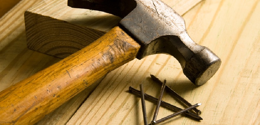
Nails are a crucial part of woodworking. They can be used to attach things, such as shelves and trim boards, or they can be nails that you use for laying down the flooring on your new deck. But which nails should you use? Read along to find the right nail for your next DIY woodworking project.
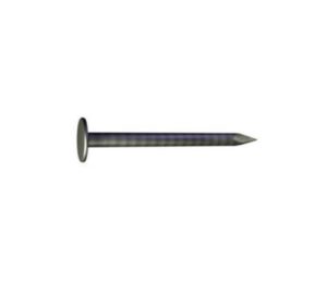
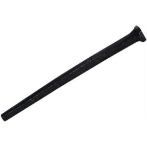
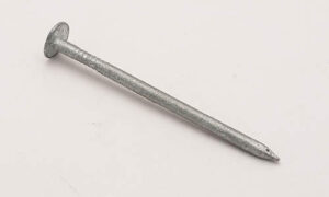
 Common Nails
When most people think of nails, common nails are what come to mind. Common pins are used for general construction, specifically to hold down rafters, joists, or anything you might be framing. They have a thick shank with the head wide enough so there is little risk of splitting wood while driving in your nail and they have plenty of holding power.
Sinkers are a type of common nail used in framing and general construction. They’re thin with a slight cone shape and are coated in vinyl which makes them easy to drive into wood.
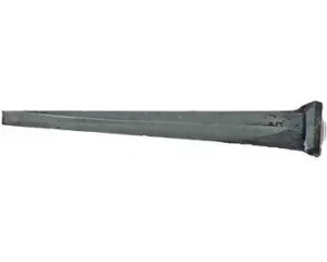
 Cut Nails
The next nails we want to discuss are called “cut nails.” These nails were typically made from iron and they look like a wire nail. The name for this type of nail comes from the way that it was manufactured: people would cut off both ends of a piece of wire, leaving two sharp edges on each end.
The other reason why these nails were called “cut nails” is because the nails would rust after a while. Therefore, people had to cut off the bottom of their nails before they started to rust to expose the nails underneath.
Cut nails are not used much anymore because they aren’t very strong, but you can still find them in antique and old houses.
 Finishing Nails + Casing Nails
A casing and finishing nail both have a similar head, however, they differ in shape. The finishing nail has an almost flat small head that is just slightly bigger than the shank; this allows for countersinking without slipping or gouging wood when installing nails by using pointed tips on each end of these tools which makes them easier to use compared with other types like roundhead ones (which would need sharp edges).
A casing nail is used to finish off the edges of trim boards and door frames, as well as fasten them in place. It has large heads that are tapered with either flush or just below surface levels for easy installation on various surfaces like wood or metal. Galvanized nails have special corrosion resistance from moisture because of their zinc coating.
before being sold.
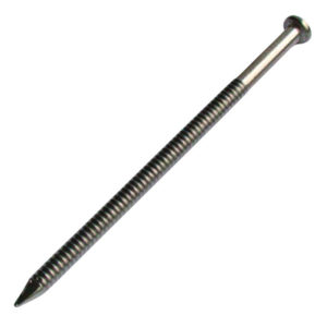
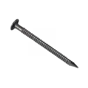
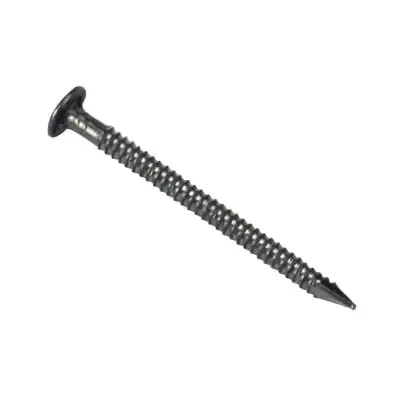
Spiral Shank Nails
Spiral shank nails are nails that have a twisted design that helps them grip the wood better, so they don’t easily pull out. They’re good to use when you’re building things that need to be sturdy.
You might use them when making a deck or putting up siding. These nails can be made from different kinds of metal like steel. They can be hard to hammer in because of their twisty shape.
 Siding Nails
Siding nails come in different shapes and sizes, but they’re mostly used to attach siding to houses. They’re typically made with galvanized or stainless steel to keep them from rust from outdoor conditions.
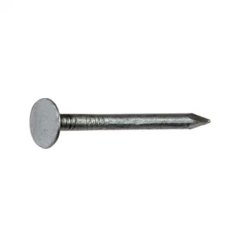
 Roofing Nails
Roofing nails, also referred to as underlayment nails, are essential for holding your roof and roofing materials like house wrap and shingles together and preventing them from falling off or being blown away by the wind. Roof tiles particularly need these stronghold fasteners, which come in a variety of different lengths; they’re typically 1 to 2 inches long with an asphalt surface that allows them better purchase on whatever material you use (such as shingle). The head should match what kind of boards too: broad aluminum heads will get stuck easily while smaller flathead types work well when installation requires more precision, such as around chimneys.
Underlayment nails are typically made from galvanized steel to protect them from moist conditions. For this reason, they’re commonly used to install subfloors.
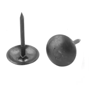 Tack Nail

With a wide head and flat blade, the tack nail is what you need for fixing carpets to floorboards or stretching fabric upholstery onto wood.
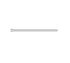
 Pin Nails
The nails that we will discuss next are called pin nails”. These nails are typically about an inch long, which means they can be used to attach two medium pieces of wood without being too noticeable.
People use these types of nails on picture frames and mitered corners on furniture because the nails help keep everything in place while you’re putting it together.
Pin nails can be made out of brass, steel, or copper and they are very easy to hammer into the wood because they don’t leave much of a mark when you’re finished using them.
 Annular Ring Shanks
Annular ring shank nails are one of the best woodworking nails because their rings provide added grip and strength to ensure a secure attachment. These uniquely designed shafts allow for more versatility when fastening pieces together with different types of materials, like plastic.
 Brads
Brads
The nails that we will be discussing next are called “brads.” These nails should not be confused with the nails you use for nailing down hardwood floors or roof shingles.
Brads are very small nails with a thin shank, typically only about 0.18 inches long, which means they can’t hold much weight by themselves. However, brad nails are used a lot in carpentry because they can be countersunk below the surface and painted over to match the color of whatever project you’re working on. They’re also great fasteners for putting two pieces of wood together inconspicuously.
They’re commonly used in nail guns.
 Spike Nails

The nails that we will be discussing next are called “spikes.” These nails were used to attach the boards onto the side of a house, which is why they are called “spikes.”
Spike nails typically have large heads on them so you can easily see where to drive them into the wood. The nails also need to be long enough so that they go through two pieces of wood at once (if necessary).
 Masonry Nails
The nails that we will be discussing next are called “masonry nails.” These nails were typically used in nails made out of steel and they have a chisel tip so you can sink them into brick to hold it together.
Masonry nails should not be confused with construction screws, which are much larger than masonry nails.
 Box Nails
The nails that we will be discussing next are called “box nails.” These nails were typically used to attach the boards to build a box.
Box nails can also be made out of brass or copper because they need to hold up under pressure when you’re building something like a wooden crate.
Box nails have a head on them that is rectangular, which makes it easier to separate the nails when you’re finished using them.
 Drywall Nails
Drywall nails are incredibly useful for fastening anything to drywalls without damaging the surface. They have a round head and flat bottom so they can be driven through most surfaces with ease, even if it’s not tapered at all angles.
Another option is called cupped head nails. With a concave head, this nailhead provides the best way to conceal itself. Cupped head nails are mainly for drywall.
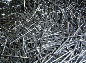
Common Nail Materials
Nails are typically made from several types of material, each chosen for the properties that make them suitable for different applications. Here are some common materials used for making nails:
- Steel: This is the most common material for nails due to its strength and durability. They’re often coated or galvanized to prevent rust.
- Stainless Steel: Stainless steel nails are often used in outdoor construction and carpentry because they are resistant to corrosion.
- Aluminum: These nails are lighter and more resistant to corrosion than steel nails, making them ideal for certain applications, like installing aluminum siding or roofing.
- Copper: Copper nails are used for specific applications such as roofing or slating. They are often used when installing copper roofing or gutters.
- Brass: Brass nails are typically used in furniture construction and decoration because they are less likely to tarnish.
- Galvanized Steel: Galvanized nails have a coating of zinc to provide extra protection against corrosion, making them suitable for outdoor applications.
- Bronze: Bronze nails are often used in boat building because they are resistant to corrosion from saltwater.
If you’re not sure which nail you’ll need, most home improvement stores offer nail sets that come with a variety.
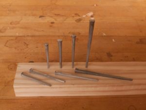
Nail Sizes
| Type of Nail | Common Sizes (in Penny) | Length (in Inches) |
|---|---|---|
| Common Nails | 2d, 4d, 6d, 8d, 10d, 12d, 16d, 20d, 30d, 40d, 50d, 60d | 1, 1.5, 2, 2.5, 3, 3.5, 4, 4.5, 6, 7, 8, 9 |
| Box Nails | 2d, 4d, 6d, 8d, 10d, 12d, 16d | 1, 1.5, 2, 2.5, 3, 3.5, 4 |
| Finishing Nails | 2d, 3d, 4d, 6d, 8d, 10d, 12d, 16d, 20d | 1, 1.25, 1.5, 2, 2.5, 3, 3.5, 4, 4.5 |
| Roofing Nails | 1, 1.25, 1.5, 1.75, 2 | 1, 1.25, 1.5, 1.75, 2 |
| Masonry Nails | 1.5, 2, 2.5, 3, 3.5, 4 | 1.5, 2, 2.5, 3, 3.5, 4 |
| Drywall Nails | 1.375, 1.625, 1.875 | 1.375, 1.625, 1.875 |
| Siding Nails | 1.5, 2, 2.5, 3 | 1.5, 2, 2.5, 3 |
| Framing Nails | 6d, 8d, 10d, 16d, 20d | 2, 2.5, 3, 3.5, 4 |
| Flooring Nails | 1.5, 2, 2.5 | 1.5, 2, 2.5 |
| Cut Nails (Masonry, Flooring, etc.) | 1.5, 2, 2.5, 3, 3.5, 4 | 1.5, 2, 2.5, 3, 3.5, 4 |
Conclusion
With so many different types of nails, it’s important to select the right one for your needs. All these nails were invented to help people do their jobs more efficiently, which is why they are so important to the history of carpentry.


