CALL US TODAY

CALL US TODAY

CNC Lathe Machine 1440

cnc masters 1440 lathe
, Get a quote

From: $10,985.00

Categories: ,

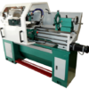
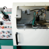
CNC BARON DOVETAIL COLUMN TABLE TOP MILL 3 AXIS CONTROL W/MOTORS CABLED (115VAC), W/COMPUTER VARIABLE SPINDLE (2HP) CONTROL (240VAC, SINGLE PHASE), GEAR HEAD, HANDWHEELS, X/Y BALLSCREWS W/PRE-LOADED NUTS, HOME SWITCHES, ONE-SHOT OIL LUBE, MASTER MX OPERATING SOFTWARE, AND USERā€™S MANUAL.


***Test out the Master MX to run your CNC Mill and be sure to check out the video here:Ā Ā Master MX Intro Video

CNC Masters presents a new CNC Mill, The CNC Baron, to our line ofĀ CNC milling machines. It is specifically designed for the machinist who needs both efficient and compact equipment at an excellent value. The CNC Baron Milling Machine is turn-key, and easy to both learn and operate. The CNC Baron Milling Machine is durable with a cast iron body without the size of a larger machine. With the smaller frame of the CNC Baron, it is perfect for large and small manufacturing plants, machine shops, and a variety of other institutions that require the mass production of a single part. Our custom CNC Master software is included with every purchase of out CNC mills. Our software runs on Windows operating systems. The CNC Baron Milling Machine comes with a one year warranty. In addition to a one year warranty, our company provides comprehensive quality testing on all of our machines.

Compare to Max

Customer satisfaction is our number one priority here at CNC Masters. We offer product support for the CNC Baron Mill and its operational software by phone or e-mail for as long as you or your company owns the CNC machine. We even transfer this support offer when the machine is sold to someone else. Click below for a hassle free quick quote for freight costs. If you have any questions, we are just a phone call or email away.

  • Full 3 Axis (4th optional) coordinated motion control on bipolar motors.
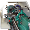
  • [X=21.5ā€³] x [Y=7ā€³] of Travel.
  • Custom CNC Master Software included
  • Works with USB connection, 64 bit operating systems: Windows 10, 8, or 7
  • Powerful X, Y, and Z axis micro-stepper motors ā€“ size 34 with 1200 in/oz torque

WE SUPPORT THE COMPLETE CNC Baron MILLING CENTER INCLUDING ITS OPERATIONAL SOFTWARE BY PHONE OR EMAIL.

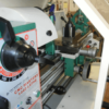
The CNC Baron Mill is durable and precise with a cast-iron body, with dovetail ways on the square column for vertical alignment. It is a versatile bench top mid-size CNC mill made for the user who needs both primary and secondary CNC machining applications.

This cnc milling machine features the performance of larger CNC models without taking up as much floor space, making it a great purchase for large and small manufacturing plants, machine shops, research institutions, colleges, universities, high schools, engineers needing quick prototype 3D parts, and operations that require the mass production of a single part.

The Baron, our new CNC mill is a great investment for business owners who lower costs by creating their own parts. The mill is simple to operate, offering immediate efficiency solutions that save the operation both time and money. The CNC Baron milling machine is proudly assembled right here in the U.S.A., and it combines both imported and American-made parts in order to offer our clients the most competitive pricing anywhere. Every milling machine at CNC Masters is hand-tested for quality and performance before we package and crate it and get it on a freight truck from our manufacturing facility in the Los Angeles area, California.

CNC milling machines have an important role in the quick and accurate production of high precision components. Since there are different types of advanced milling machines on the market, here are some basic features of these machines explained:

  1. CNC machines exist in two different forms.

    When the spindle performs horizontal cutting, it is known as horizontal milling machine, whereas the vertical machining center has its cutting tool positioned accordingly. The head of the CNC Baron Milling Machine tilts for angled drilling, horizontal milling, slotting, and more. Its dovetail ways on the column, X table, and Y saddle allow for precision alignment and movement.

  2. They involve versatile movements of both the cutter and work piece.

    Unlike conventional machining centers, the milling process involves controlled movements of both work pieces and cutters based on the integrated software control. These features can actually perform complex parts production based on versatile cutting movements, which is the reason CNC mills are available in different models ā€“ 3, 4, and 5-axis machines. The CNC Baron Mill has full 3 Axis (or optional 4 Axis) coordinated motion control on bipolar motors, which is far superior over the unipolar technology in terms of torque and power.

  3. The operation is based on a software control system.

    Most CNC milling machines are computer programmed to perform intricate milling operations that aim to minimize contact between the operator and the cutting tools.

  4. These are available in various sizes based on the sizes of the components.

    These machines have different sizes which are custom-made for producing various component sizes. The large size CNC milling machines are meant for producing large parts, and vice versa.

Precision Machining using CNC Milling has many user benefits, including:

  • Components Produced with Repetition and Accuracy
  • 3D Complex Components Made with Ease
  • Programs and Fixtures Can be Saved to Reduce Repeat Setup Costs
  • High-Speed Precision Machining Shortens Lead Times
  • Most Materials (Including Hardened Steels) Can be Cut with New Cutter Technology

The CNC Baron machine and controller are built to stock in-house in the USA. We do not buy and re-sell our CNC Driving System. So we’ll never bounce you to a third-party vendor for limited support to either their controller or another vendor’s machine.

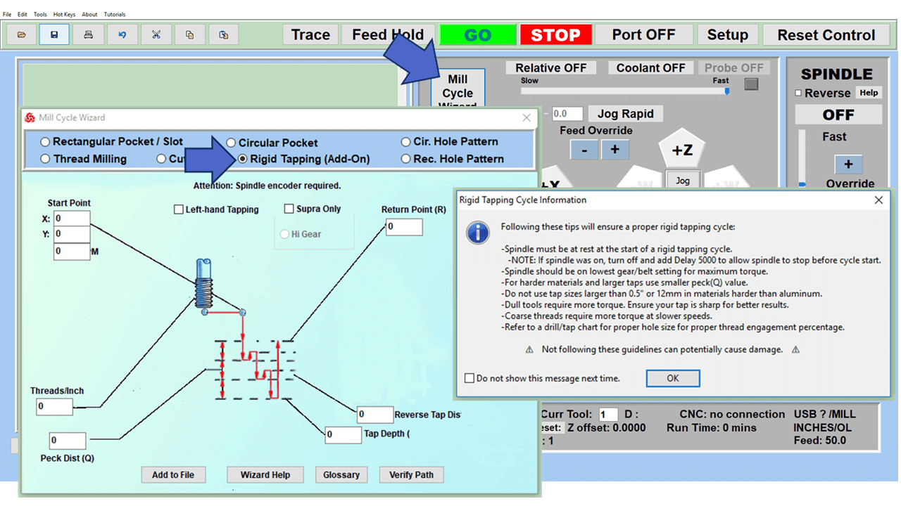
The Baron model cast iron CNC milling machine is a turn-key solution specifically designed for those who need efficiency in a compact space.Ā Ā AddĀ rigid tapping controlĀ ā€“ no need for tapping heads attachments ā€“ to tap your series of holes after just running a multiple hole peck drilling operation.Ā  Add aĀ fourth axis,Ā probe controlĀ to scan and duplicate parts, or aĀ hand held pendant controlĀ to your CNC Baron Mill.

  • This CNC milling machine is designed to work with Windows 10 64 bit operating systems through your standard USB port.
  • Powerful X, Y, and Z-axis micro-stepper motors are size 34 with 1200 oz-in. of torque. Stronger torque coupled with micro-stepping motion allows the Baron CNC milling machine to perform accurately without losing steps.
  • The minimum possible motion is 0.0002" with a minimum speed of 0.20" per minute. The maximum speed is 150" per minute on your Rapid Settings with ramp down effect to keep the cnc milling machine from jerking.
  • Full 3 Axis or optional 4 Axis coordinated motion control on bipolar motors--far superior over unipolar technology when it comes to torque and power. True Interpolation!
  • Head tilts for angled drilling, horizontal milling, slotting and more
  • Hand scraped dovetail ways with tapered gibs on the column, X table, and Y saddle for precision alignment and movement
  • One-Shot Oil Lube on all dovetails and ways
  • Hand-Wheels on each axis for manual option machining with "motor disengage" feature to retain computer spindle speed control for the cnc mill
  • X and Y Zero Backlash Ball Screws with pre-loaded ball nuts to eliminate play on the table and saddle travel, and provides precision machining down to /- 0.00025" in one inch. These custom-made precision ball screws allow for precision conventional and climb milling operations and accurate circular and contour cuts without time consuming setups.
  • The Baron cnc milling machine has the Z Axis pre-load arranged to eliminate backlash on the up/down travel
  • X and Y Direct Drives--no timing belts to adjust. This results in smoother operations and ensures accuracy unlike pulley and belt drive methods which can cause the belt to buckle causing inaccurate results. This unique design of direct drive keeps the user without having the need to change the belt or adjust as it wears down.
  • Home Reference Sensors on the X, Y, Z which saves your home/zero position as the first line of your program. This feature allows you to quickly return to the home position on any program without having to manually zero your three axes again.
  • Limit Switches on all opposite extreme ends of X, Y, & Z travel allowing you to confidently test your program without having to worry about an axis travel to its end and causing damage to machine.
  • Tool Height Compensation with Automatic Quill Retraction for easy R8 collet tool change
  • Tool Cutter Radius Offset Compensation
  • Run your tool path from any line on your program
  • Easy to Use Jogging Features and Feed Control by pc mouse or keyboard
  • Use Teach Mode Jog-Input Command to automatically write each line of your tool path as you manually jog each axis by pc mouse, keyboard, or the optional hand held remote control joystick to save as a program for repeat use.
  • Software Power Feed capabilities on X, Y, Z, and W with one click of the pc mouse for exact relative driving distance.
  • Pre-engineered for you when it comes to pitch and resolution. No tuning or calibration needed at setup. No additional parameters set-up required. Display resolution is 0.0001 micro-stepping travel. Just start using your machine.
  • Runs files from popular CAD-CAM that produce standard FANUC type G-Codes to machine or engrave intricate and detailed parts.
  • Easily build a file of commands to machine simple parts such as drilling and slot operations without the need to learn to use a CAD-CAM program.
  • Digital Read Out Display of your X, Y, Z, (and optional W) counters on your computer screen in INCHES or METRIC using your PC mouse, keyboard, or our optional Hand Held Remote Control.
  • Add other options such as 4th Axis, Rigid Tapping Control, Digital Probe, Hand Pendant Control, Coolant Control, Quick Change Tools, and Computer with Arm from our line of accessories.
  • Computer Controlled Variable Spindle Speed with gear-head to change speeds quickly while retaining torque. Program your spindle's speed in the MX Software through M-codes, simple English conversational commands, and on the fly with your PC mouse.
  • Hand-Wheels on each axis for manual option machining with ā€œmotor disengageā€ feature to retain computer spindle speed control for the cnc mill
  • This CNC mill features a user-friendly setup for any beginner or experienced machinist. Easy to learn and operate. See our testimonials.
  • The Baron cnc milling machine is backed by our CNC MASTERS ONE YEAR WARRANTY or extend it for two more years.
  • Unlimited ā€œLife-Longā€ Tech Support step-by-step trouble shooting and walk-through process by email or phone Monday-Friday during normal business hours, pacific time, for as long as your company owns the machine. (Nominal fee for second hand owners.)
  • Easy to repair, replace parts, and maintain unlike costly servo systems that need to be serviced.
  • Free MX Operating Software Updates for original owners as long as the hardware can support it.

Reviews

There are no reviews yet.

Be the first to review “CNC Lathe Machine 1440”

Your email address will not be published. Required fields are marked *

Slide 1

29. Create a Peck Drilling Program in Circular or Rectangular Patterns
Using the Circular or Rectangular Drilling Wizards, you can program the machine to drill an un-limited series of holes along the X and Y planes. Program it to drill straight through to your total depth, use a high-speed pecking cycle, or deep hole pecking cycle. You can program the cut-in depth and return point for a controlled peck drill application to maximize chip clearance.

Slide 1

20. Change up to 30 tools with compensation, and store your tool offsets for other programs
The MX supports…

Slide 1

21. Use the optional ATC rack up to 8 tools for milling, drilling, and rigid tapping applications
The CNC Masters Automatic Tool Changer Rack and Tools (US Patent 9,827,640B2) can be added to any CNC Masters Milling Machine built with the rigid tapping encoder option. The tutorial will guide you through the set-up procedure using the ATC tools.

Slide 1

22. Use the optional Rigid Tapping Wizard without the need for tapping head attachments
When you order your CNC Masters machine, have it built with the optional rigid tapping encoder. You can take any drill cycle program and replace the top line with a tapping code created by the wizard to tap your series of holes up to 1/2ā€ in diameter.

Slide 1

23. Use the optional Digital Probe to scan the profile and/or pockets of your fun/hobby type designs to write your tool path program and machine out a duplicate of your original design To ā€œsurfaceā€ scan an object, you can program the probe along the X or Y plane. The stylus will travel over the part starting on the left side front corner of the object and work its way to the end of the part on the right side. Depending on how the stylus moves, it will record linear and interpolated movements along the X, Y, and Z planes directly on the MX Editor.
To ā€œpocketā€ scan an object containing a closed pocket such as circles or squares, the scan will start from the top front, work its way inside of the pocket, and scan the entire perimeter of the pocket.
Under the Setup of the MX software you will find the Probe Tab which will allow you to calibrate and program your probe. Your ā€œProbe Stepā€, ā€œFeedā€, and ā€œData Filterā€ can also be changed on the fly while the probe is in the middle of scanning your object.

Slide 1

24. Use work offsets G54-G59 for nesting applications
The work offsets offer you a way to program up to six different machining locations. Itā€™s like having multiple 0.0 locations for different parts. This is very useful especially when using sub-routines/nesting applications.

Slide 1

25. Create a Rectangular Pocket / Slot with our selection of Wizards to help you build a tool path program
The Cycle Wizards for the mill or lathe makes it easy to create a simple tool path without needing to use a CAD and CAM software.
On this Wizard, the Rectangular Pocket / Slots, can be used to form a deep rectangular pocket into your material or machine a slot duplicating as many passes needed to its total depth.

Slide 1

26. Create a Circular Pocket Wizard
Input the total diameter, the step down, and total depth and the code will be generated.

Slide 1

27. Do Thread Milling using a single point cutter Wizard

Slide 1

28. Cut a gear out using the Cut Gear Wizard with the optional Fourth Axis

Slide 1

19. Disable the axis motors to manually hand crank each axis into place
Easily de-energize the axis motors by clicking [Disable Motors] to crank each axis by hand, and then press [Reset Control] to re-energize the axis motors.

Slide 1

30. The MX interface can easily be interchanged from Mill Mode to Lathe Mode
Use this interface for your CNC Masters Lathe. It contains all the same user-friendly features and functions that comes in Mill Mode. Simply go to the Setup page and change the interface.

Slide 1

31. Use Tool Change Compensation or the optional Auto Tool Changer Turret if your application requires more than one tool in a single program
You can offset the length and angle of each tool and record it under Tools in your Setup. The program will automatically pause the latheā€™s movement and spindle allowing you to change out your tool, or allowing the optional ATC Turret to quickly turn to its next tool and continue machining.
On the MX interface, you also have four Tool Position buttons. Select your desired T position, and the auto tool post will quickly turn and lock itself to that position.

Slide 1

32. Use the Lathe Wizard Threading Cycle to help you program your latheā€™s internal or external threads in inches or metric

Slide 1

33. Use the Lathe Wizard Turning / Boring Cycle to help you program simple turning and boring cycles without having to go through a CAM or writing a long program with multiple passes

Slide 1

34. Use the Lathe Wizard Peck Drilling Cycle to help you program your drill applications or for face grooving

Slide 1

35. Facing / Grooving / Part Off Cycle Wizards ā€“ with Constant Surface Speed
These cycles can be used with Constant Surface Speed allowing the spindle speed to increase automatically as the diameter of the part decreases giving your application a consistent workpiece finish. With CSS built into the wizard, there is no need to break down the cycle into multiple paths and multiple spindle speed changes.

Slide 1

36. This is our list of supported G and M codes which can be found under Tools > G Code/ M Code List in the MX
If you plan to use a third-party CAM software to generate your tool path program, use a generic FANUC post processor and edit it to match our list of codes. As an option, we also sell Visual mill/turn CAM software which comes with a guaranteed post processor for our machines to easily generate your tool path programs based on your CAD drawings.

Slide 1

37. Our pledge to you…

Slide 1

10. Run each tool path independently to study its movement
1. Run the machine on Trace mode. You can run each tool path independently, one line at a time to study the tool path movement on the machine to verify the position of the application and if any fixture/vise is in the way of the cutterā€™s path.

2. You can also verify your program by clicking on the Trace and Draw buttons together. This will allow you to view each tool path independently one line at a time in the Draw Window.

Slide 1

2. Clutter Free Interface
The MX is engineered for the CNC MASTERS machine so you do not have to fiddle with a detailed complicated configuration that can be overwhelming. Just load in the MX and start machining!2. Clutter Free Interface
The MX is engineered for the CNC MASTERS machine so you do not have to fiddle with a detailed complicated configuration that can be overwhelming. Just load in the MX and start machining!

Slide 1

3. Features Tour and Tutorials Included
The Features Tour will give you a quick run-down on all the features the MX can do for you. The Tutorials are easy to follow even for the first time CNC machinist.
Feel free to download the MX on any of your computers. We recommend downloading the MX along with your CAD and CAM software there at the comfort of your office computer to generate your tool path programs. You donā€™t need to be hooked up to the machine either to test your program in simulation mode.

Slide 1

4. Navigate and Edit Your Program through the MX interface with Ease
With a few clicks of the mouse or using touch screen technology, you can easily navigate through the MX interface importing saved programs into the Editor from the File drop down menu. Using standard windows features to edit your program you can then lock the Editor Screen to avoid accidental editing, and if you need to insert a line in the middle of a program, just click on [ReNum] to re-number your tool path list.
You can create a program or import CAM generated G-code tool paths into the Editor
The X Y and Z W arrow jog buttons are displayed from the point of view of the cutter to avoid confusion when the table and saddle are moving. You can also adjust your spindle speed and coolant control while jogging each axis.

Slide 1

5. Feed Hold ā€“ Pause in the Middle of your Program
Feed Hold lets you pause in the middle of a program. From there you can step through your program one line at time while opting to shut the spindle off and then resume your program.
You can also write PAUSE in the middle of your program and jog each axis independently while your program is in pause mode.

Slide 1

6. Hot Keys
Hot Keys is an alternative method to easily control your machine using your hard or touch screen keyboard. One can press P to pause a program, press S to turn Spindle On, G to run a program, Space Bar to Stop, J to record your individual movements one line at a time to create a program in teach mode.

Slide 1

7. Pick Menu ā€“ for conversational mode programming
Write FANUC style G-codes directly into the Editor or select commands off the [Pick] menu and write your tool path program in conversational mode such as what is written in the Editor box. You can even mix between conversation commands and G-codes in the same program.

Slide 1

8. Pick Menu List of Options
Use commands such as MOVE, SPINDLE ON/OFF, COOLANT ON/OFF, PAUSE, DELAY, GO HOMEā€¦. to write your tool path programs in conversational mode.

Slide 1

9. Draw the Tool Path to verify it before pressing Go
Hit Draw to view your tool path program drawing, check out its run time, or even simulate the tool path in 3D mode. This can be helpful to quickly verify your program before running it. You can also slow down or speed up the drawing or simulation process.
You can also hit Go within the Draw Window itself to verify the cutterā€™s position on the machine. The current tool path will be highlighted and simultaneously draw out the next path so you can verify what the cutter will be doing next on the program.

Slide 1

MX Software ā€“ Easy to Use, Easy to Learn ā€“ Included with your machine purchase
The MX software is designed to work seamlessly with your CNC Masters machine. It is made to work with Windows PC ā€“ desktop, laptop, or an all in one ā€“ on standard USB. Use it on Windows 8 or 10 64-bit operating systems.
No internal conversion printer/serial port to USB software or additional conversion hardware is used with the MX.

Slide 1

11. Counters display in Inches or Millimeters ā€“ Continuous Feed
1. When running a program, the counters will display a ā€œreal-timeā€ readout while the machine is in CNC operation without counting ahead of the movement.
2. The current tool path is highlighted while the machine is in operation without causing slight interruptions/pauses as the software feeds the tool path to the machine. The MX internally interprets a program ten lines ahead to allow for ā€œcontinuous machiningā€ avoiding slight interruptions as the machine waits for its next tool path command.
3. ā€œRun Timeā€ tells you how long it takes to run your tool path program.

Slide 1

12. Use the ā€œGo From Lineā€ command to start in the middle of your program
If you ever need to begin your program from somewhere in the middle of it, use [Go From Line] which you can find under Tools. The Help guide will walk you through how to position the cutter without losing its position on the machine.

Slide 1

13. Exact Motion Distance without over-stepping on an axis while jogging
Use ā€œRelative ONā€ to enter a specific coordinate to jog any of your axes to an exact location without having to write a program. Itā€™s like using ā€œpower feedā€ but easier. You can jog an exact distance on any of the axes without needing to keep the key pressed down and mistakenly over-step the movement releasing your finger too slowly off the jog button.
Letā€™s say you need to drill a hole exactly 0.525ā€ using the Z. So you enter 0.525 in the Z box. Next, adjust the JOG FEED RATE slider for the desired feed rate. Then ā€œclick onceā€ on the +Z or -Z button to activate the travel. In this case you click once the -Z button first to drill the hole exactly 0.525ā€. Then click once on the +Z button to drive the axis back up 0.525ā€.

Slide 1

14. Teach Mode ā€“ Jog Input
You can create a tool path program by storing each point-to-point movement by simply jogging an axis one at a time. Click on either of the Jog Input buttons to store each movement on the Editor Screen. You can then add Spindle ON, feed commands, and press GO to run the new program as needed. This is a great feature to help you learn to create a program by the movements you make on the machine without necessarily writing out an entire program first.

Slide 1

15. Override on the fly to adjust the Jog Feed to Rapid or the Spindle Speed during the middle of a program
1. Jog Feed and Rapid with Override: You can adjust feeds using the slider from slow minimum 0.1ā€³ per minute to a rapid of 100ā€³ per minute of travel. You can even micro-step your jog as low as 0.01ā€/min. The [-][+] buttons allow you to fine tune feeds in 5% increments while the program is in motion.
2. Spindle Speed with Override: You can adjust speeds using the slider from a slow minimum RPM to the max RPM according to the machine setup. The [-][+] buttons allow you to fine tune feeds in 5% increments while the program is in motion.

Slide 1

16. Adjust Counters using Pre-Set if you cannot begin the program from 0.00
In a situation where you cannot begin your cutter at itā€™s 0.00 location, you can ā€œPre-Setā€ directly into the counters by typing in your beginning coordinate. You can press Go from here to run your program. You can also ā€œzero allā€ or ā€œzeroā€ your counters independently. With one click of the [Return to 0.0] button, all axes will travel back to its respective 0.0 on the machine.

Slide 1

17. Set and Save your 0.00 position for future runs
Set and save your 0.00 position on the machine. These coordinates will be recorded as the first line of the program in the Editor Screen. Should you desire to return to this program at a later date, you only have to click on the Set Zero Return button. This will command the machine to automatically jog each axis to its saved ā€œsetā€ 0.00 position according to the recorded coordinates at the first line of the program.

Slide 1

18. Create a ā€œHomeā€ position to clear your application and run multiple times
Letā€™s say you need to machine one application times 100 pieces. This usually requires a jig to retain that physical 0.00 position. But in this case, you want the program to end with a clearance of the axes to easily switch out the next piece of stock and start again. With Save Home, you have the ability to save this offset (home) position while still retaining your Set Zero position where the machine will mill your part out. Pressing [Save Home] will record this new position under the Set Zero line in your program.
Pressing [Go Home] will jog your axes back to your ā€œsaved homeā€ position where you originally pressed the Save Home command. You can also input GO_HOME from the Pick Menu as its own tool path in your program. At the completion of your program the axes will end at your Home position. Replace your part, then press [Return to 0.0] button to allow the axes to return to its zero position, and press Go to start your next run.

previous arrow
next arrow