Milling Machines with CNC
Milling machines with CNC are an integral part of the manufacturing industry with a unique design that sets them apart from their vertical counterparts mill machine without CNC. These CNC machines feature a horizontally oriented spindle that holds cutting tools, allowing chips to fall away more quickly and making these milling machines particularly suitable for heavy-duty tasks and high-volume production. Horizontal milling machines enhance manufacturing productivity and precision because multiple cutters work simultaneously on different surfaces of the workpiece. Check out this CNC Mill on sale right now. Click here.
Milling machines are among the most commonly used machine tools in modern manufacturing. They’re found in assembly lines, small tool-and-die shops, home workshops, and just about everywhere in between. Almost every industry uses milling machines from small mills in high-end scientific labs to machining centers in the automotive industry.
Milling machines are popular with manufacturers and engineers because they help produce more complex parts than the average 3D printer or manual craft tool can handle. On the consumer side, hobbyists and DIYers use milling machines at home for small parts and woodworking projects.
If you’re in the market for a new mill, we’ve got you covered. This article has background on milling machines including types, uses, and features so that you’ll know how to choose a machine that helps you get the results you need. This guide gives you everything you need to buy your milling machine confidently.
What does a milling machine do?
Milling machines can machine materials such as metal, plastic, or wood. Mills use cutting tools including end mills, face mills, and drills. They can feature high-quality cast iron construction, variable speed capability, power feeds, and milling cutters that move along the X, Y, and Z axes. Milling machines are essential tools in manufacturing, offering the flexibility to produce a wide range of products with precision and efficiency. Their versatility and accuracy make them indispensable in many industries from automotive and aerospace to furniture and mold production.
They perform various milling operations like slotting, keyway cutting, and drilling to more complex functions like contouring, die sinking, and 3D milling. Unlike lathe machines, where a workpiece is mounted between the headstock and tailstock and above the bed, mills fasten the workpiece to the table.
Mills handle a wider range of materials, offer greater precision and control, and use a rotating cutting tool to remove material. Routers are used for woodworking and some plastics and perform lighter, faster cuts and that employ a spinning bit to shape or hollow out an area on the workpiece.
Types of Milling Machines
Milling machines primarily fall into two types based on the orientation of the main spindle: horizontal and vertical. Vertical milling machines are used for plunge cuts and drilling, while horizontal milling machines perform tasks requiring specific heavy-duty machining. Both types use rotating cutting tools (end mills, bed mills, face mills, drills, etc.) spinning at speeds up to 20,000 RPM.
Some machine tools combine elements of a milling machine with other common tools. Small mills certainly aren’t the only variation on the milling machine theme. Here are the most popular types of milling machines and their uses.
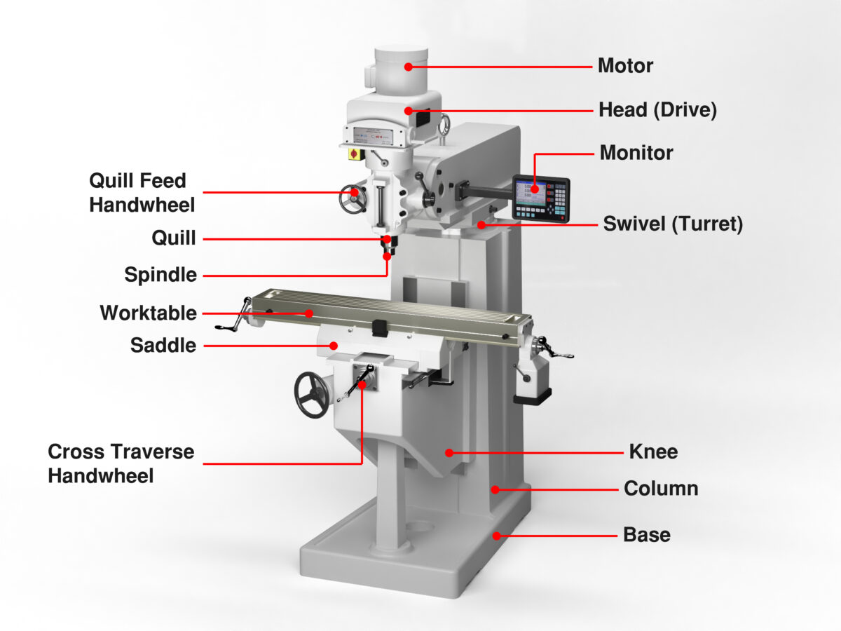
Vertical Milling Machines
Characterized by a vertically oriented spindle axis, vertical milling machines are extensively used in manufacturing industries because of their versatility and precision. The vertical orientation of the cutting tool allows for more complex shapes and unique designs to be machined with accuracy. It enables manufacturers to perform various tasks like keyway cutting, surface milling, drilling, and multi-dimensional contouring. Vertical milling machines are the go-to method for producing surfaces because they are a more efficient way of face milling than grinders, abrasives, and planers. Industries such as automotive, aerospace, and electronics rely on these machines for producing intricate parts and components.
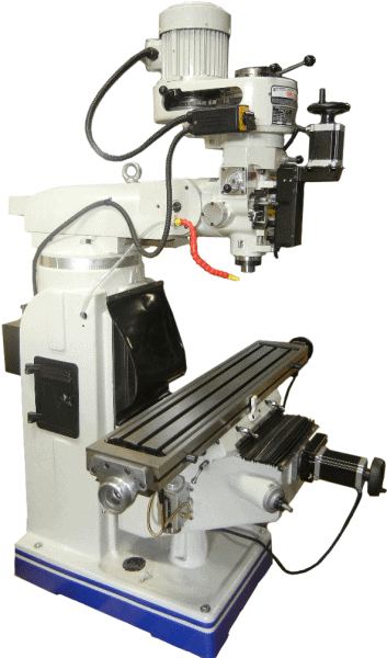
Knee Mills
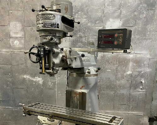 Sometimes referred to as a turret mill, Bridgeport-type mill, mill drill, or even a drilling machine, the knee-type vertical milling machine is a highly versatile piece of equipment commonly employed in various industries for its capacity to handle multiple tasks. It can even take the place of a stand-alone drill press. Its defining feature is a vertically adjustable worktable (the “knee”), which provides flexibility in handling different sizes and types of workpieces. This machine can perform multiple operations on the same workpiece including drilling, boring, and milling. The knee-type vertical milling machine’s adaptability to diverse tasks and materials (from metalworking to plastics) makes it an invaluable asset as a toolroom mill or on the shop floor.
Small Milling Machines
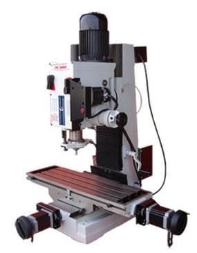
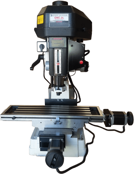 Also known as benchtop and mini-mills, desktop milling machines are compact yet powerful tools that have considerably expanded manufacturing and prototyping. Most mini-milling machines are vertical mills, making them highly versatile. They carve and shape materials such as wood, metal, or plastic with excellent precision. Ideal for small-scale projects, engineers and hobbyists commonly utilize them to create intricate designs and parts.
These machines can also be used in educational settings, offering students hands-on experience in manufacturing and design principles. They have diverse uses such as producing electronic circuit boards and crafting intricate jewelry designs. Modern mini-mills with CNC technology have increased versatility and even more applications. In the next section, CNC technology will be explained in more detail.
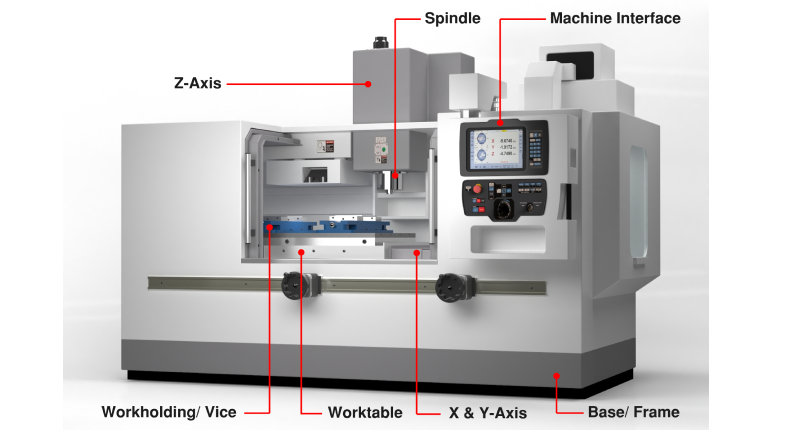
CNC Milling Machines
Computer Numerical Control (CNC) milling machines are revolutionary devices in manufacturing and prototyping. They utilize a computer-controlled system to automate the complex processes involved in milling which significantly enhances precision, reliability, and speed. These complex 4-axis and 5-axis milling machines feature software and programming that helps “run” the milling machine. Whether a horizontal or vertical machining center, the CNC milling machine features electronic variable speed and coolant systems for prolonged protection. Because it translates computer commands into mechanical motion, CNC milling machines offer unparalleled control over production.
CNC milling machines are capable of remarkable efficiency. Traditional manual mills are labor-intensive and require manual skills. CNC milling machines automate the production process, reducing the need for human intervention and thereby reducing errors. These machines can operate continuously over extended periods to increase productivity.
CNC milling machines are the top-end option because they provide a high-precision solution to parts manufacturers. These machines are versatile and can handle various materials including metals like aluminum, steel, plastics, and even wood. This versatility and high precision make them suitable for multiple industries including automotive, aerospace, and electronics where customers demand excellent accuracy and consistency. For more information on these CNC machining centers, please read our guide on CNC machines.
Milling Machine Must-Haves
When it comes time to purchase a milling machine, what are the most important things to consider? There’s no one universal milling machine, and every machine will likely be better at some milling operations than others. But before you make your choice, consider these three primary considerations:
Reasonable Price
How much does a milling machine cost?
- For a hobbyist desktop mill, a solid machine costs roughly $2,500 to $7,500.
- CNC knee mills start at $15,000 and go up to $75,000.
- 3-Axis Mills begin around $45,000 and go as high as $100,000.
- Production mills and lathes are $250,000 and up, depending on size and features. These machines are found in larger shops for machining complex, heavy-duty parts.
Appropriate Size
The size of the mill determines the type of work it can perform. Clearly, you will need an industrial-sized machining center for a machine that can handle industrial-sized workpieces. Metal fabrication shops handling more significant pieces of metal will want either full-size mills or larger benchtop models. You may want a reinforced milling head on a vertical mill, or you may jump straight to a horizontal mill.
Mini-milling machines are smaller than their full-size counterparts. Some mini-mills are the typical desktop mills, able to handle sizable parts yet small enough to fit on top of a workbench. Other mills fall into the “micro milling machine” category which are tiny mills for intricate or detailed work like jewelry. Most home milling machines fall into this category.
Remember that there’s a stability trade-off with smaller mills. In general, the larger the mill, the more stable it is. Mills can be clamped to the top of a workbench or bolted directly to the floor; the latter is preferable if you need precise and heavy-duty cutting. While clamping your mini mill on top of a bench offers substantially more accessibility and ease of use, it comes at the expense of some stability.
Advanced Features
As you read through the description and list of features for a possible milling machine purchase, you need to hone in on the features that are important for your needs. What features should you look for? Here are a few features that we recommend:
- Digital readouts (DROs): Digital readouts make a mill much more user-friendly. They’ll also help the operator keep cuts accurate and precise.
- 3- or 4-axis movement: The more axes of movement, the greater the range of operations possible on the mill. X-axis, Y-axis, and Z-axis movement is the standard. Tools with more axes will likely swivel the cutting tool around the part, engaging it from different angles. Mills with a rotary table allow the workpiece itself to swivel, providing access without re-mounting the part.
- Cast-iron construction: Cast iron isn’t just sturdy; it’s heavy. Weight on a mini-mill is an advantage. It adds stability and improves precision.
- Spindle speed and horsepower specs: High-speed spindles and heavy-duty horsepower engines increase drilling and milling capacity.
- Head tilt: Many mills have geared heads capable of cutting at an angle, adding flexibility.
Precision
For the ultimate in precision cutting, you’ll want a CNC mill. CNC programming allows an operator to program the exact series of operations for the mill to make, creating precise and accurate cuts.
CNC mills can also be more easily integrated with design workflows. A hobbyist might design a custom part on a CAD program, export the vector file to their CNC mini mill, and create a custom program to fabricate his part.
In many situations, however, the task at hand does not require CNC capabilities. Manual mills are less precise, designed for only one operator, and have no computer-controlled movement, making them more affordable than their CNC counterparts. Since adding CNC capabilities will make your new mill considerably more expensive, carefully evaluate whether you need the benefits of the added functionality.
Buying Tips
Now that you know what you need from the milling machine, what should you look for in a suitable manufacturer?
- Wide product range
- Look for companies catering to the machinist industry who sell high-quality lathes and mills of all shapes and sizes.
- Excellent customer support
- Customer support doesn’t just come after a sale! Reach out to companies for advice who are willing to guide you through purchasing, not just try to upsell a more expensive machine. Also, check the warranty policy for each machine and manufacturer.
- Detailed specialist knowledge
- Machine tools include specialist and hobbyist fields such as desktop mills, jewelry machine tools, or DIY. If applicable, look for a company that serves your niche.
- Quality construction
- From collet to shank, the best machine tool manufacturers use only the best parts. Look for a company that doesn’t skimp on quality components, and you’ll find one that produces high-end milling machines.
Popular Milling Machine Brands
Even among the best in the industry, certain brands stand out for their quality, durability, and precision, while others are known for their low prices. Ideally, you will find the manufacturer with the best combination of high performance, affordability, and service for your needs. The following brands have a strong reputation while serving different industry niches.
- Jet sells manual mill drills for under $4,000 and manual Bridgeport-type knee mills in the $17,000 to $21,000 range.
- Grizzly offers lightweight, low-horsepower mills for around $2,000.
- Wen is another brand you might encounter with mill drills under $2,000.
- CNC Masters has high-quality CNC knee mills under $15,000, CNC lathes for less than $12,000, and CNC desktop mills starting under $6,000.
- Haas machining centers are found among mid-price range CNC mills since they provide a cost-effective alternative to higher-priced brands without compromising quality or performance.
- Okuma has vertical and horizontal machining centers offering precision and flexibility to enhance productivity, reduce downtime, and save money for companies in the manufacturing sector.
- Mazak offers advanced technology and high-level productivity exclusively for larger corporations willing and able to spend hundreds of thousands of dollars for each machine tool.
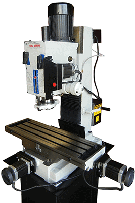
Our Choice: The Supra Mill
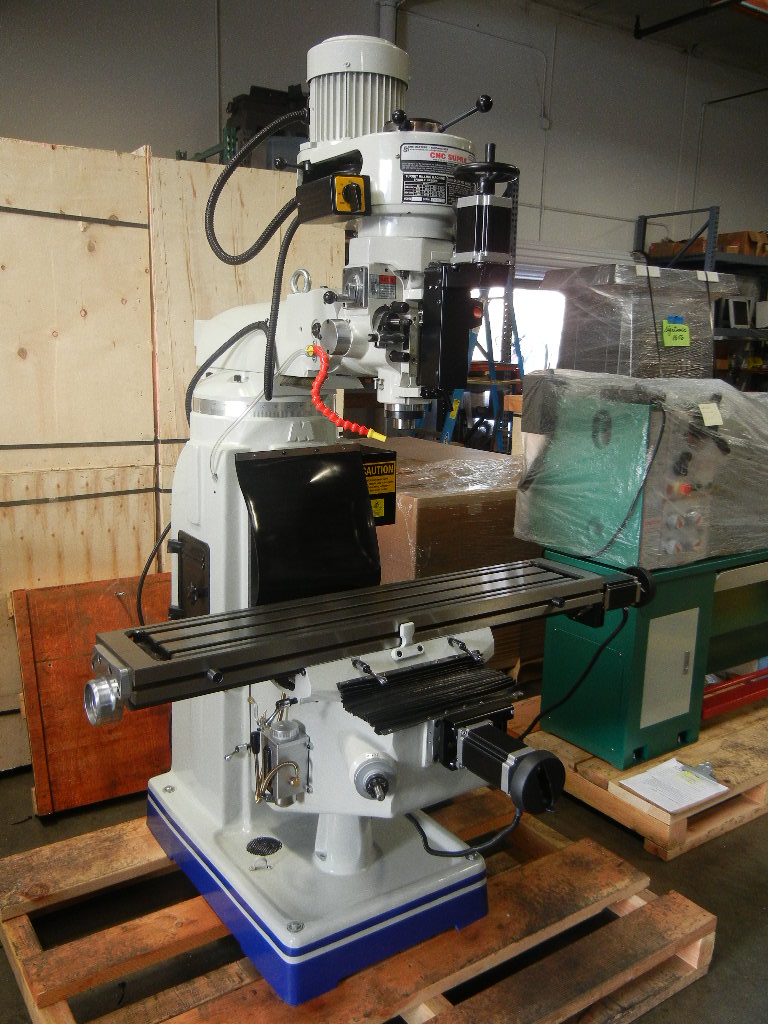
The SUPRA CNC vertical knee mill from CNC Masters will make any shop more productive. This versatile machine works for hobbyists, machine shops, product development, high production work, engraving, and teaching tools in vocational-technical schools and science labs. And if you need a manual mill for a few quick operations, the Supra converts from CNC to manual mode effortlessly.
Look at a few of the specifications for the CNC SUPRA 10×54 Vertical Knee Mill:
- Table travel (Longitudinal X-axis): 35.5”
- Saddle travel (Y-axis): 15.5”
- Knee travel (Z-axis): 18”
- Table size: 10” x 54”


