In stock:
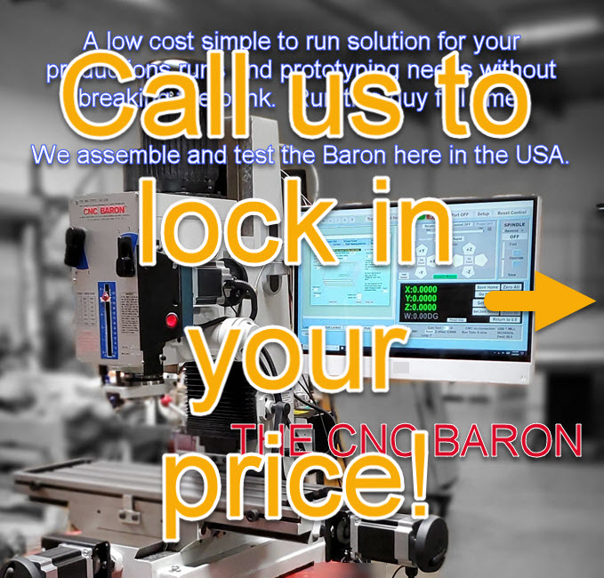
Pre-Owned Baron Mill with MX software, coolant control and machine stand, $3,999! 6 month warranty. Call for details. 626-962-9300 x1
DESCRIPTION
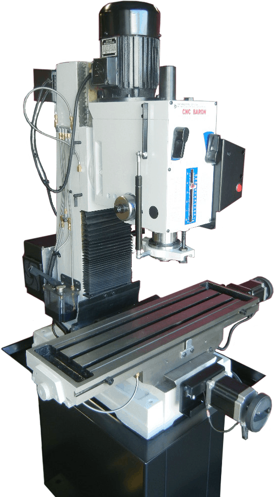
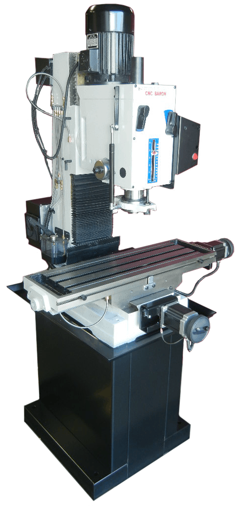
MILLING MACHINE TABLE TOP WITH 3 AXIS CNC CONTROL (115VAC), W/COMPUTER VARIABLE SPINDLE (2HP) CONTROL (240VAC, SINGLE PHASE), GEAR HEAD, HANDWHEELS, X/Y BALLSCREWS W/PRE-LOADED NUTS, HOME SWITCHES, ONE-SHOT OIL LUBE, MASTER MX OPERATING SOFTWARE, AND USER’S MANUAL.
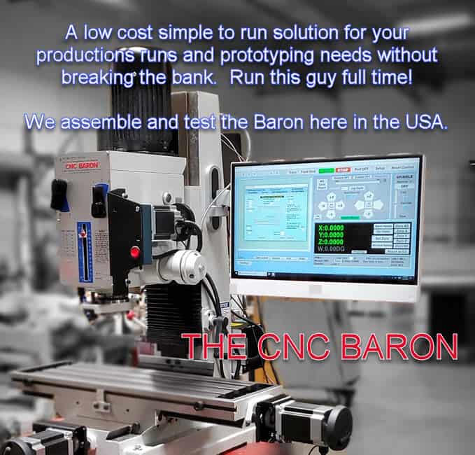
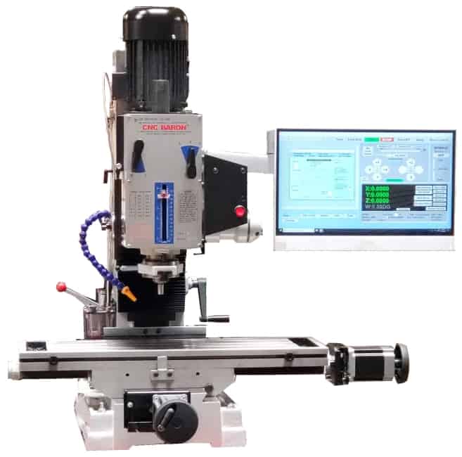
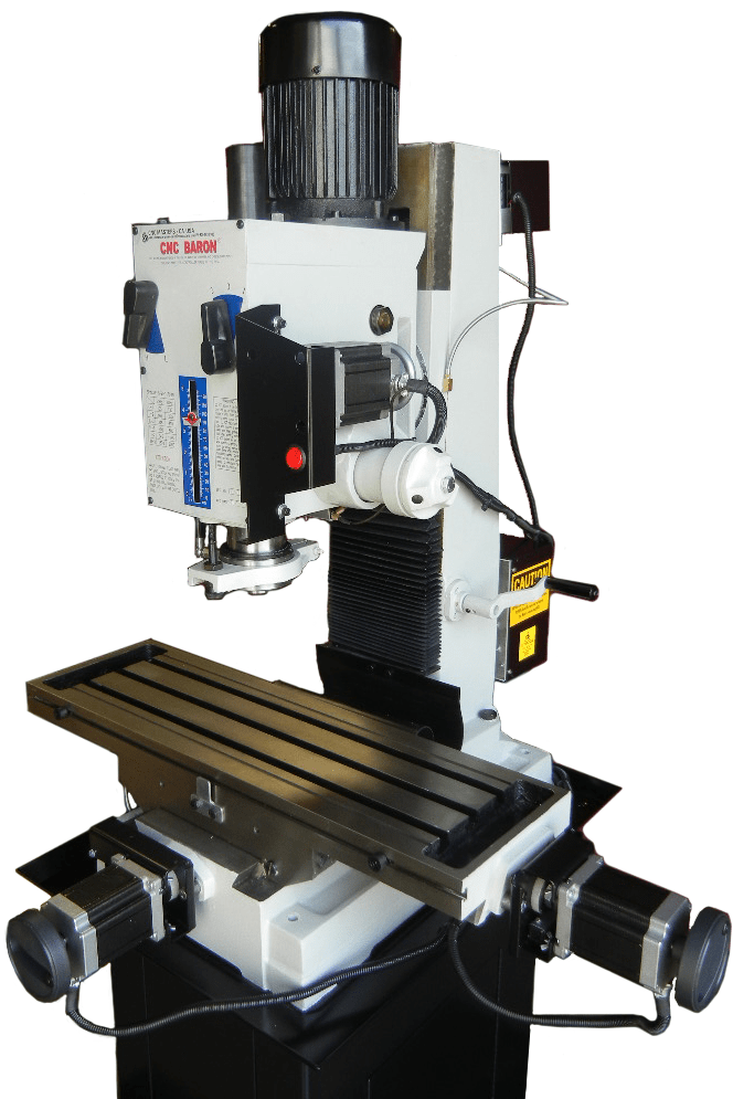
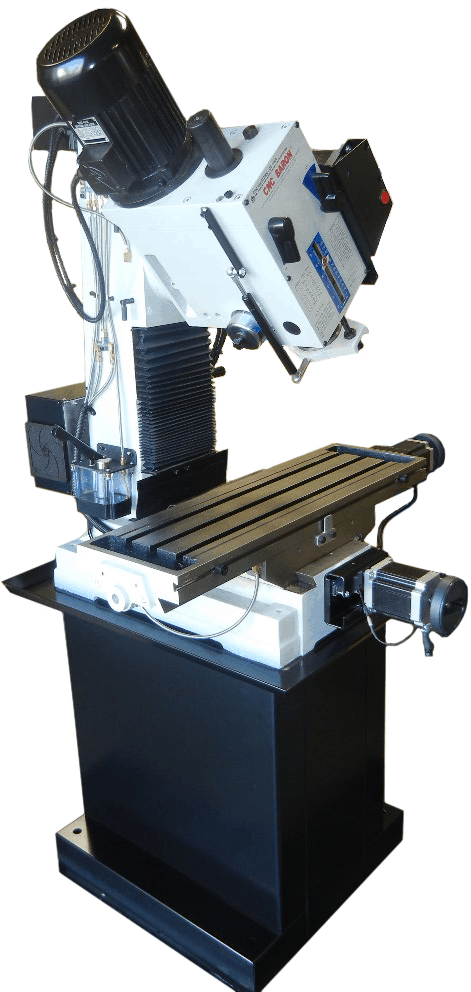
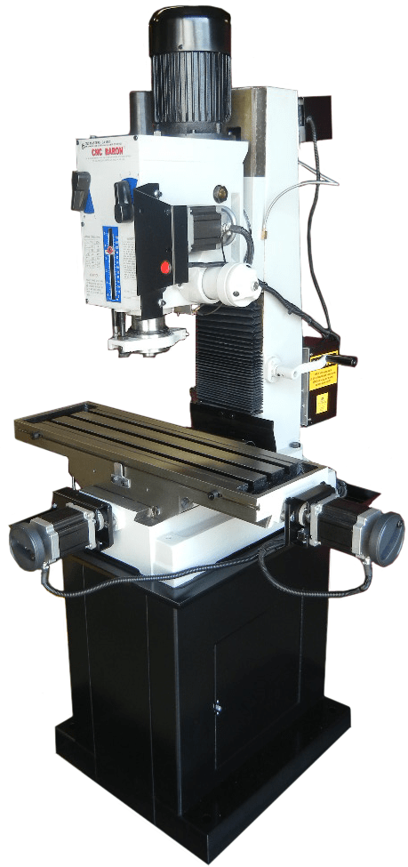
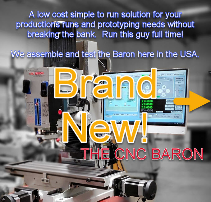
The CNC Baron is specifically designed for the machinist who needs both efficient and compact equipment at an excellent value. The CNC Baron Milling Machine is turn-key, and easy to both learn and operate. The CNC Baron Milling Machine is durable with a cast iron body without the size of a larger machine. With the smaller frame of the CNC Baron, it is perfect for large and small manufacturing plants, machine shops, and a variety of other institutions that require the mass production of a single part without taking up much space. Run this machine full time! Our custom CNC Master MX software is included with every purchase of out CNC mills. Our software runs on Windows operating systems. The CNC Baron Milling Machine comes with a one year warranty. In addition to a one year warranty, as the original owner you get tech support without expiration.
- Full 3 Axis (4th optional) coordinated motion control on bipolar motors.
- [X=21.5″] x [Y=7″] of Travel.
- Custom CNC Master Software included
- Works with USB connection, 64 bit operating systems: Windows 10 or 11
- Powerful X, Y, and Z axis micro-stepper motors – size 34 with 1200 in/oz torque
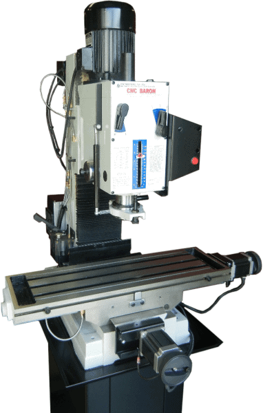
The CNC Baron Mill is durable and precise with a cast-iron body, with dovetail ways on the square column for vertical alignment. It is a versatile bench top mid-size CNC mill made for the user who needs both primary and secondary CNC machining applications.
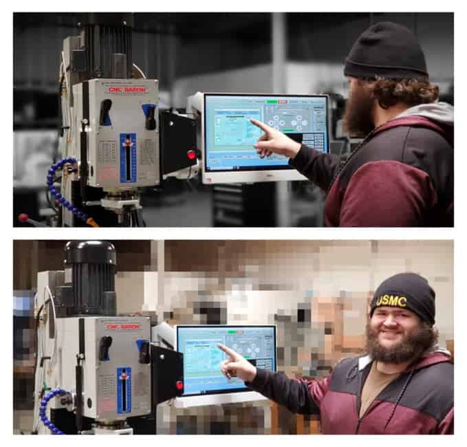
The Baron CNC mill is a great investment for business owners who lower costs by creating their own parts. The milling machine is simple to operate, offering immediate efficiency solutions that save the operation both time and money. The CNC Baron milling machine is proudly assembled right here in the U.S.A., and it combines both imported and American-made parts in order to offer our clients the most competitive pricing anywhere. Every milling machine at CNC Masters is hand-tested for quality and performance before we package and crate it and get it on a freight truck from our manufacturing facility in the Los Angeles area, California.
CNC milling machines have an important role in the quick and accurate production of high precision components. Since there are different types of advanced milling machines on the market, here are some basic features of these machines explained:
CNC machines exist in two different forms.
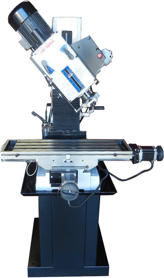
When the spindle performs horizontal cutting, it is known as horizontal milling machine, whereas the vertical machining center has its cutting tool positioned accordingly. The head of the CNC Baron Milling Machine tilts for angled drilling, horizontal milling, slotting, and more. Its dovetail ways on the column, X table, and Y saddle allow for precision alignment and movement.
They involve versatile movements of both the cutter and work piece.
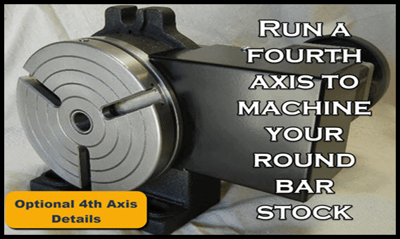
Unlike conventional machining centers, the milling process involves controlled movements of both work pieces and cutters based on the integrated software control. These features can actually perform complex parts production based on versatile cutting movements, which is the reason CNC mills are available in different models – 3, 4, and 5-axis machines. The CNC Baron Mill has full 3 Axis (or optional 4 Axis) coordinated motion control on bipolar motors, which is far superior over the unipolar technology in terms of torque and power.
The operation is based on a software control system.
Most CNC milling machines are computer programmed to perform intricate milling operations that aim to minimize contact between the operator and the cutting tools.
These are available in various sizes based on the sizes of the components.
These machines have different sizes which are custom-made for producing various component sizes. The large size CNC milling machines are meant for producing large parts, and vice versa.
Precision Machining using CNC Milling has many user benefits, including:
- Components Produced with Repetition and Accuracy
- 3D Complex Components Made with Ease
- Programs and Fixtures Can be Saved to Reduce Repeat Setup Costs
- High-Speed Precision Machining Shortens Lead Times
- Most Materials (Including Hardened Steels) Can be Cut with New Cutter Technology
The CNC Baron machine and controller are built to stock in-house in the USA. We do not buy and re-sell our CNC Driving System. So we’ll never bounce you to a third-party vendor for limited support to either their controller or another vendor’s machine.
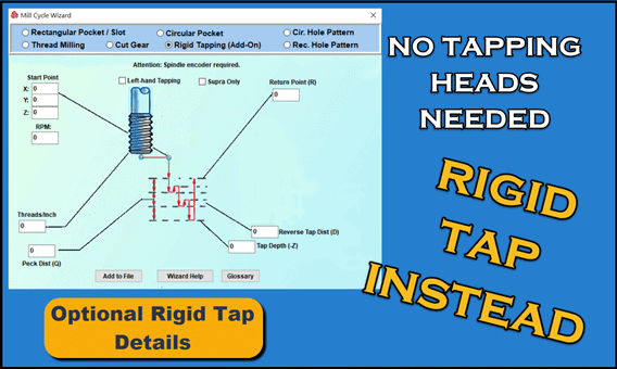
Add rigid tapping control – no need for tapping heads attachments – to tap your series of holes after just running a multiple hole peck drilling operation. Add a fourth axis, probe control to scan and duplicate parts, or a hand held pendant control to your CNC Baron Mill.
CHOOSE OPTIONS
TECH SPECS
CNC Baron® Milling Machine Specifications
| Model | CNC BARON |
|---|---|
| X Axis: Left/Right Table Travel | 21.5″ (546 mm) |
| Y Axis: Front/Back Saddle Travel | 7″ (175 mm) |
| Z Axis: Spindle Up/Down Travel | 5″ (127 mm) |
| Maximum Distance from Spindle Nose to Table | 18″ (450 mm) |
| Swivel Angle of Headstock at Perpendicular Direction | +/- 90 Degrees |
| Drilling Capacity | .75″ (19.05 mm) |
| Face Mill Capacity | 3” (76.2 mm) |
| End Mill Capacity | .75″ (19.05mm) |
| Working Area of Table – Table Specs with T-Slots | 31.5″ x 9.5″ (800 mm x 240 mm) |
| Spindle Taper | R8 Collet |
| Spindle Motor and Power – Computer Variable Spindle Control | 2 HP; 220-240vac single phase |
| Spindle 6 Speeds Gear Head with Oil Bath for Stronger Torque | 60 HZ: 196, 388, 662, 893, 1768, 3000 RPMs 50 HZ: 163, 323, 552, 744, 1473, 2500 RPMs |
| Limit Switches on Opposite Ends of Travel | X Y Z |
| Max Rapid on X Y Z | 150 IPM (3810 mm/m) |
| One-Shot Oil Pump | Lubricates Dovetail Ways, Tapered Gibs, and Quill |
| Machine Body and Head | Cast Iron |
| Computer Connection to Control Unit | USB Port, Windows 10 or 11 PC 64 bit |
| X Y Z W Stepper Motors | NEMA 34, Bi-Polar, 1200 oz-in of torque |
| Overall Length w/out X motor (left end of table to right end) | 35.375” (898.525 mm) |
| Overall Width w/out controllers and Y motor (front to back of machine) | 27.75” (704.85 mm) |
| Overall Length (left end of table to right end of X motor handle) | 42” (1067 mm) |
| Overall Width (back of machine with controllers to front end of Y motor handle) | 42” (1067 mm) |
| Machine Height (without machine stand) | 42” (1060 mm) |
| Machine Stand Height | 30” (760 mm) |
| Machine Stand Chip Pan | 30.75” x 22.875” (781 mm x 581 mm) |
| Machine Base 4 Bolt Pattern to Stand | 22.25” x 12.75” (505.15 mm x 323.85 mm) |
| Max Movement Area | 62.5″ (1587.5 mm) x 42″ (1067 mm) |
| Weight | 800 lbs. |
Baron CNC Milling Machine Power Requirements
| CNC | BARON | MILLING | MACHINE |
|---|---|---|---|
| 110VAC dedicated circuit with a NEMA 5-15R | |||
| 220 to 240 VAC, single phase with ground @ 15 amp service required |
Baron CNC Milling Machine Tolerances
| Accuracy | +/- 0.003″ (or 0.0762 mm) |
|---|---|
| Repeatability | within 0.0005″ (or 0.0127 mm) |
| Resolution | 0.0002″ (or 0.006 mm) |
NOTE: The CNC Control Unit is available in either 110 or 220VAC models. The 110 VAC model will be shipped unless otherwise requested.
Can the Baron CNC Milling machine fit through a 35” – 36” door way?Yes it can. Move the milling machine in diagonally. The X and Y motors are disconnected from the axes for shipping purposes. You can remove the hand cranks off each motor, stick ½” bolt into them and easily mount and secure the hand cranks directly to the X and Y ball screws to drive and position the axes so that you can move the machine through the doorway without having to dismantle it. However, it is certainly possible to dismantle the milling machine by removing a few bolts. Call or email us to walk you through this procedure.
Can I fit the Baron cnc machine in a basement?It is possible. Make sure your stair ways can support the weight of the machine. Use a refrigerator type dolly, strap the machine to it. Use ¾” plywood to rest over the stairs, use a hoist with ratchet to gently lower the machine down the stairs. Follow all recommended safety cautions.
FEATURES
- This CNC milling machine is designed to work with Windows 10 or 11, 64 bit operating systems through your standard USB port.
- Powerful X, Y, and Z-axis micro-stepper motors are size 34 with 1200 oz-in. of torque. Stronger torque coupled with micro-stepping motion allows the Baron CNC milling machine to perform accurately without losing steps.
- The minimum possible motion is 0.0002″ with a minimum speed of 0.20″ per minute. The maximum speed is 150″ per minute on your Rapid Settings with ramp down effect to keep the cnc milling machine from jerking.
- Full 3 Axis or optional 4 Axis coordinated motion control on bipolar motors–far superior over unipolar technology when it comes to torque and power. True Interpolation!
- Head tilts for angled drilling, horizontal milling, slotting and more
- Hand scraped dovetail ways with tapered gibs on the column, X table, and Y saddle for precision alignment and movement
- One-Shot Oil Lube on all dovetails and ways
- X and Y Zero Backlash Ball Screws with pre-loaded ball nuts to eliminate play on the table and saddle travel, and provides precision machining down to /- 0.00025″ in one inch. These custom-made precision ball screws allow for precision conventional and climb milling operations and accurate circular and contour cuts without time consuming setups.
- The Baron cnc milling machine has the Z Axis pre-load arranged to eliminate backlash on the up/down travel
- X and Y Direct Drives–no timing belts to adjust. This results in smoother operations and ensures accuracy unlike pulley and belt drive methods which can cause the belt to buckle causing inaccurate results. This unique design of direct drive keeps the user without having the need to change the belt or adjust as it wears down.
- Home Reference Sensors on the X, Y, Z which saves your home/zero position as the first line of your program. This feature allows you to quickly return to the home position on any program without having to manually zero your three axes again.
- Limit Switches on all opposite extreme ends of X, Y, & Z travel allowing you to confidently test your program without having to worry about an axis travel to its end and causing damage to machine.
- Tool Height Compensation with Automatic Quill Retraction for easy quick tool change when doing multiple tool changes in a single program. Check out the quick change tools which are needed for multiple tool changes.
- Run your tool path from any line on your program
- Easy to Use Jogging Features and Feed Control by pc mouse or keyboard
- Use Teach Mode Jog-Input Command to automatically write each line of your tool path as you manually jog each axis by pc mouse, keyboard, or the optional hand held remote control joystick to save as a program for repeat use.
- Software Power Feed capabilities on X, Y, Z, and W with one click of the pc mouse for exact relative driving distance.
- Pre-engineered for you when it comes to pitch and resolution. No tuning or calibration needed at setup. No additional parameters set-up required. Display resolution is 0.0001 micro-stepping travel. Just start using your machine.
- Runs files from popular CAD-CAM that produce standard FANUC type G-Codes to machine or engrave intricate and detailed parts.
- Easily build a file of commands to machine simple parts such as drilling and slot operations without the need to learn to use a CAD-CAM program.
- Digital Read Out Display of your X, Y, Z, (and optional W) counters on your computer screen in INCHES or METRIC using your PC mouse, keyboard, or our optional Hand Held Remote Control.
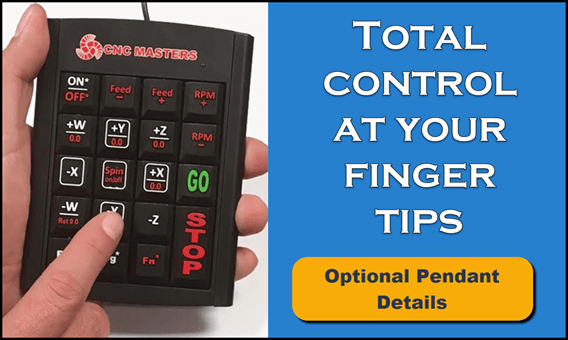
- Add other options such as 4th Axis, Rigid Tapping Control, Digital Probe, Hand Pendant Control, Coolant Control, Quick Change Tools, and Computer with Arm from our line of accessories.
- Computer Controlled Variable Spindle Speed with gear-head to change speeds quickly while retaining torque. Program your spindle’s speed in the MX Software through M-codes, simple English conversational commands, and on the fly with your PC mouse.
- Hand-Wheels on each axis for manual option machining with “motor disengage” feature to retain computer spindle speed control for the cnc mill
- This CNC mill features a user-friendly setup for any beginner or experienced machinist. Easy to learn and operate. See our testimonials.
- The Baron cnc milling machine is backed by our CNC MASTERS ONE YEAR WARRANTY or extend it for two more years.
- Unlimited “Life-Long” Tech Support step-by-step trouble shooting and walk-through process by email or phone Monday-Friday during normal business hours, pacific time, for as long as your company owns the machine. (Nominal fee for second hand owners.)
- Easy to repair, replace parts, and maintain unlike costly servo systems that need to be serviced.
- Free MX Operating Software Updates for original owners as long as the hardware can support it.

Click the image to enlarge or to view as a slideshow.

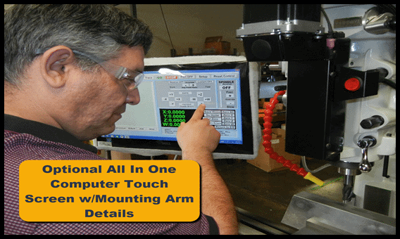
The MX software is designed to work seamlessly with your CNC Masters machine. It is made to work with Windows PC – desktop, laptop, or an all in one – on standard USB. Use it on Windows 10 or 11 64-bit operating systems. No internal conversion printer/serial port to USB software or additional conversion hardware is used with the MX.

The MX is engineered for the CNC MASTERS machine so you do not have to fiddle with a detailed complicated configuration that can be overwhelming. Just load in the MX and start machining!
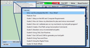 The Features Tour will give you a quick run-down on all the features the MX can do for you. The Tutorials are easy to follow even for the first time CNC machinist. Feel free to download the MX on any of your computers. We recommend downloading the MX along with your CAD and CAM software there at the comfort of your office computer to generate your tool path programs. You don’t need to be hooked up to the machine either to test your program in simulation mode.
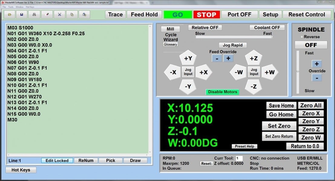
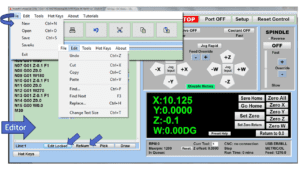 With a few clicks of the mouse or using touch screen technology, you can easily navigate through the MX interface importing saved programs into the Editor from the File drop down menu. Using standard windows features to edit your program you can then lock the Editor Screen to avoid accidental editing, and if you need to insert a line in the middle of a program, just click on [ReNum] to re-number your tool path list. You can create a program or import CAM generated G-code tool paths into the Editor. The X Y and Z W arrow jog buttons are displayed from the point of view of the cutter to avoid confusion when the table and saddle are moving. You can also adjust your spindle speed and coolant control while jogging each axis.
 Feed Hold lets you pause in the middle of a program. From there you can step through your program one line at time while opting to shut the spindle off and then resume your program. You can also write PAUSE in the middle of your program and jog each axis independently while your program is in pause mode.
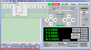 Hot Keys is an alternative method to easily control your machine using your hard or touch screen keyboard. One can press P to pause a program, press S to turn Spindle On, G to run a program, Space Bar to Stop, J to record your individual movements one line at a time to create a program in teach mode.
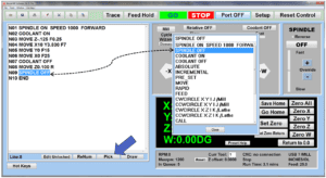 Write FANUC style G-codes directly into the Editor or select commands off the [Pick] menu and write your tool path program in conversational mode such as what is written in the Editor box. You can even mix between conversation commands and G-codes in the same program.
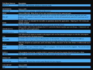 Use commands such as MOVE, SPINDLE ON/OFF, COOLANT ON/OFF, PAUSE, DELAY, GO HOME…. to write your tool path programs in conversational mode.
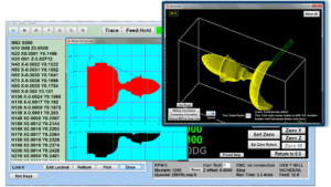 Hit Draw to view your tool path program drawing, check out its run time, or even simulate the tool path in 3D mode. This can be helpful to quickly verify your program before running it. You can also slow down or speed up the drawing or simulation process. You can also hit Go within the Draw Window itself to verify the cutter’s position on the machine. The current tool path will be highlighted and simultaneously draw out the next path so you can verify what the cutter will be doing next on the program.
 1. Run the machine on Trace mode. You can run each tool path independently, one line at a time to study the tool path movement on the machine to verify the position of the application and if any fixture/vise is in the way of the cutter’s path. 2. You can also verify your program by clicking on the Trace and Draw buttons together. This will allow you to view each tool path independently one line at a time in the Draw Window.
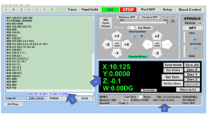 1. When running a program, the counters will display a “real-time” readout while the machine is in CNC operation without counting ahead of the movement. 2. The current tool path is highlighted while the machine is in operation without causing slight interruptions/pauses as the software feeds the tool path to the machine. The MX internally interprets a program ten lines ahead to allow for “continuous machining” avoiding slight interruptions as the machine waits for its next tool path command. 3. “Run Time” tells you how long it takes to run your tool path program.
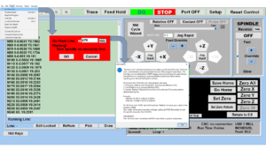 If you ever need to begin your program from somewhere in the middle of it, use [Go From Line] which you can find under Tools. The Help guide will walk you through how to position the cutter without losing its position on the machine.
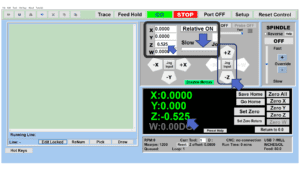 Use “Relative ON” to enter a specific coordinate to jog any of your axes to an exact location without having to write a program. It’s like using “power feed” but easier. You can jog an exact distance on any of the axes without needing to keep the key pressed down and mistakenly over-step the movement releasing your finger too slowly off the jog button. Let’s say you need to drill a hole exactly 0.525” using the Z. So you enter 0.525 in the Z box. Next, adjust the JOG FEED RATE slider for the desired feed rate. Then “click once” on the +Z or -Z button to activate the travel. In this case you click once the -Z button first to drill the hole exactly 0.525”. Then click once on the +Z button to drive the axis back up 0.525”.
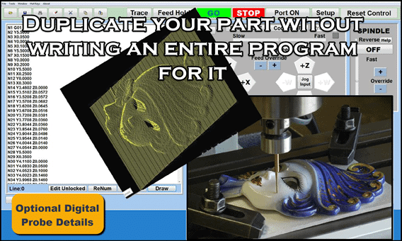
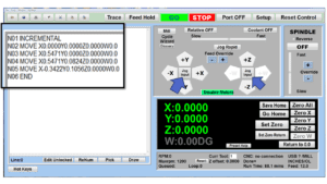 You can create a tool path program by storing each point-to-point movement by simply jogging an axis one at a time. Click on either of the Jog Input buttons to store each movement on the Editor Screen. You can then add Spindle ON, feed commands, and press GO to run the new program as needed. This is a great feature to help you learn to create a program by the movements you make on the machine without necessarily writing out an entire program first.
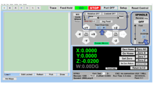 1. Jog Feed and Rapid with Override: You can adjust feeds using the slider from slow minimum 0.1″ per minute to a rapid of 100″ per minute of travel. You can even micro-step your jog as low as 0.01”/min. The [-][+] buttons allow you to fine tune feeds in 5% increments while the program is in motion. 2. Spindle Speed with Override: You can adjust speeds using the slider from a slow minimum RPM to the max RPM according to the machine setup. The [-][+] buttons allow you to fine tune feeds in 5% increments while the program is in motion.
 In a situation where you cannot begin your cutter at it’s 0.00 location, you can “Pre-Set” directly into the counters by typing in your beginning coordinate. You can press Go from here to run your program. You can also “zero all” or “zero” your counters independently. With one click of the [Return to 0.0] button, all axes will travel back to its respective 0.0 on the machine.
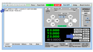 Set and save your 0.00 position on the machine. These coordinates will be recorded as the first line of the program in the Editor Screen. Should you desire to return to this program at a later date, you only have to click on the Set Zero Return button. This will command the machine to automatically jog each axis to its saved “set” 0.00 position according to the recorded coordinates at the first line of the program.
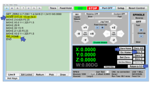 Let’s say you need to machine one application times 100 pieces. This usually requires a jig to retain that physical 0.00 position. But in this case, you want the program to end with a clearance of the axes to easily switch out the next piece of stock and start again. With Save Home, you have the ability to save this offset (home) position while still retaining your Set Zero position where the machine will mill your part out. Pressing [Save Home] will record this new position under the Set Zero line in your program. Pressing [Go Home] will jog your axes back to your “saved home” position where you originally pressed the Save Home command. You can also input GO_HOME from the Pick Menu as its own tool path in your program. At the completion of your program the axes will end at your Home position. Replace your part, then press [Return to 0.0] button to allow the axes to return to its zero position, and press Go to start your next run.
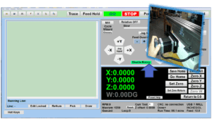 Easily de-energize the axis motors by clicking [Disable Motors] to crank each axis by hand, and then press [Reset Control] to re-energize the axis motors.
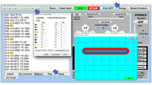 The MX supports… Tool Height Compensation allows for accurate height offsets when making a tool change using quick change tools within a program. Up to 30 tool changes can be made. This feature can be very effective for improved productivity if your application requires several tool changes. Store a library of tool offsets in the Setup > Tools window. You can choose any tool 1 – 30 by writing a T# command on its own line in a program. With a T command, the spindle will automatically shut off and retract up to exchange tools without needing to write extra lines of code. Tool Radius Offsets can also be done. If you choose to use a G41/G42 for a radius tool offset, you can enter the diameter in the Tools Window under Setup, and the machine will offset the radius of the tool. Diameter of Tool: By entering the size of the cutter in the Setup > Tools Window, you can also view the tool paths according to cutter size denoted by a different color in the Draw window.
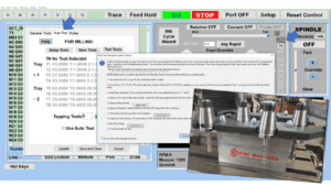 The CNC Masters Automatic Tool Changer Rack and Tools (US Patent 9,827,640B2) can be added to any CNC Masters Milling Machine built with the rigid tapping encoder option. The tutorial will guide you through the set-up procedure using the ATC tools.
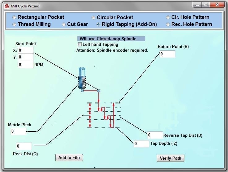
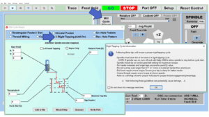 When you order your CNC Masters machine, have it built with the optional rigid tapping encoder. You can take any drill cycle program and replace the top line with a tapping code created by the wizard to tap your series of holes up to 1/2” in diameter.
 To “surface” scan an object, you can program the probe along the X or Y plane. The stylus will travel over the part starting on the left side front corner of the object and work its way to the end of the part on the right side. Depending on how the stylus moves, it will record linear and interpolated movements along the X, Y, and Z planes directly on the MX Editor. To “pocket” scan an object containing a closed pocket such as circles or squares, the scan will start from the top front, work its way inside of the pocket, and scan the entire perimeter of the pocket. Under the Setup of the MX software you will find the Probe Tab which will allow you to calibrate and program your probe. Your “Probe Step”, “Feed”, and “Data Filter” can also be changed on the fly while the probe is in the middle of scanning your object.
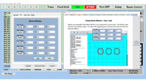 The work offsets offer you a way to program up to six different machining locations. It’s like having multiple 0.0 locations for different parts. This is very useful especially when using sub-routines/nesting applications.
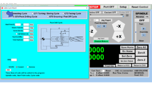
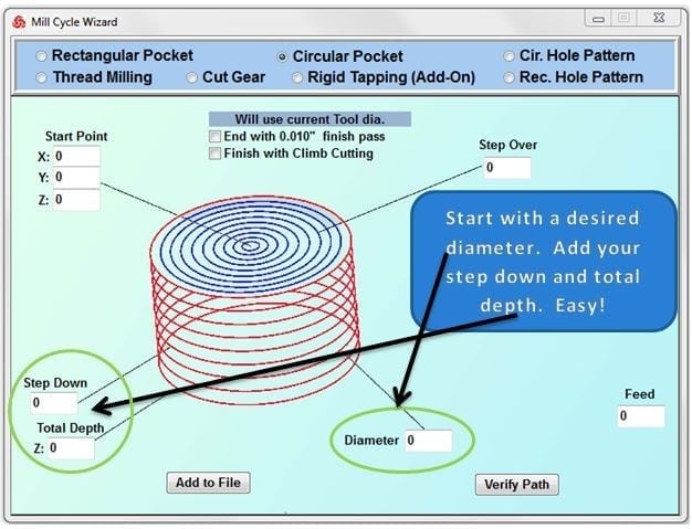
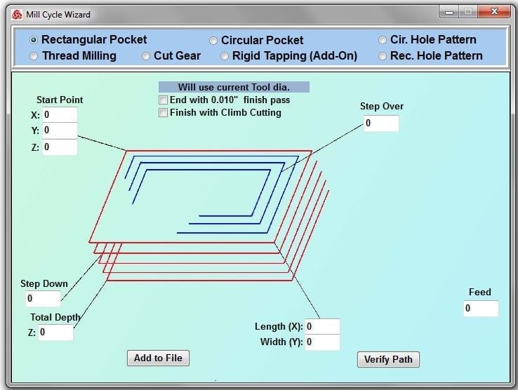
 The Cycle Wizards for the mill or lathe makes it easy to create a simple tool path without needing to use a CAD and CAM software. On this Wizard, the Rectangular Pocket / Slots, can be used to form a deep rectangular pocket into your material or machine a slot duplicating as many passes needed to its total depth.
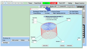 Input the total diameter, the step down, and total depth and the code will be generated.
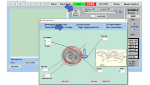
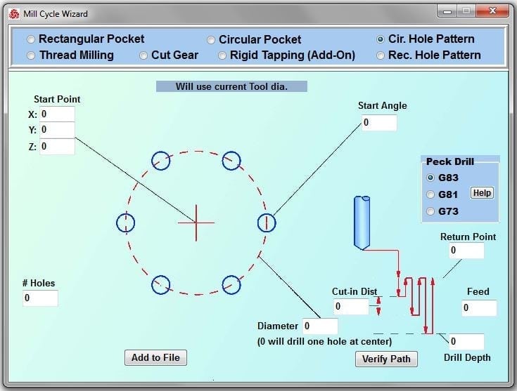
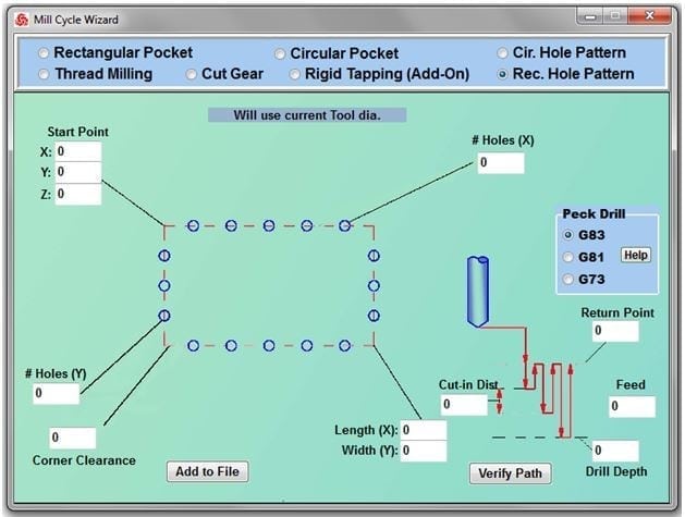
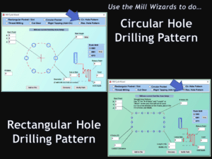 Using the Circular or Rectangular Drilling Wizards, you can program the machine to drill an un-limited series of holes along the X and Y planes. Program it to drill straight through to your total depth, use a high-speed pecking cycle, or deep hole pecking cycle. You can program the cut-in depth and return point for a controlled peck drill application to maximize chip clearance.
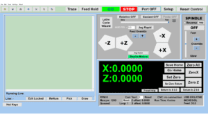 Use this interface for your CNC Masters Lathe. It contains all the same user-friendly features and functions that comes in Mill Mode. Simply go to the Setup page and change the interface.
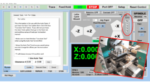 You can offset the length and angle of each tool and record it under Tools in your Setup. The program will automatically pause the lathe’s movement and spindle allowing you to change out your tool, or allowing the optional ATC Turret to quickly turn to its next tool and continue machining. On the MX interface, you also have four Tool Position buttons. Select your desired T position, and the auto tool post will quickly turn and lock itself to that position.
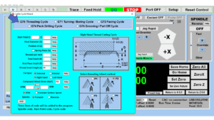
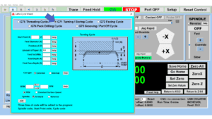
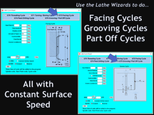 These cycles can be used with Constant Surface Speed allowing the spindle speed to increase automatically as the diameter of the part decreases giving your application a consistent workpiece finish. With CSS built into the wizard, there is no need to break down the cycle into multiple paths and multiple spindle speed changes.
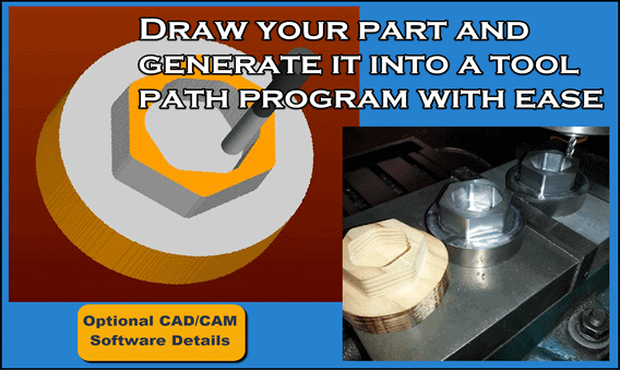
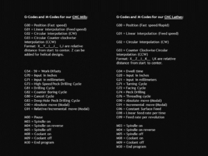 If you plan to use a third-party CAM software to generate your tool path program, use a generic FANUC post processor and edit it to match our list of codes. As an option, we also sell Visual mill/turn CAM software which comes with a guaranteed post processor for our machines to easily generate your tool path programs based on your CAD drawings.
MX Software Included
Try out the new Master MX. The MX works exclusively with the CNC Masters MX Numerical Control Units now being built with our CNC milling and lathe machines. The MX software is included with your CNC Masters Machine.
Download Master MX slide presentation in PDF
Click here to view list of Videos demonstrating the Master Software
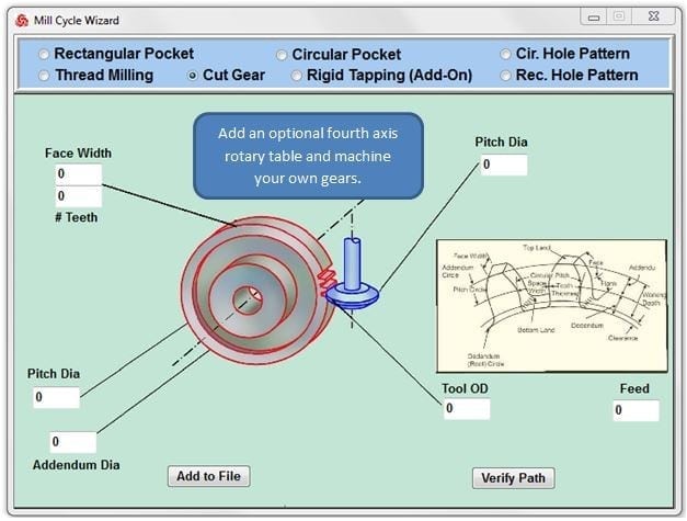
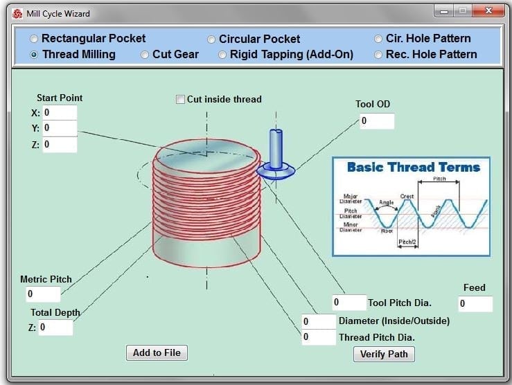
Easy Wizard Cycles for quick tool path creations such circle patterns and profiles, slots, rectangular pocketing, thread milling, rigid tapping (with optional encoder kit) and peck drilling applications.
- Import FANUC based G and M code programs from your CAM software. We also offer VisualCAD/CAM as an option which comes with a guaranteed post processor made for CNC Masters machinery.
G00 = Position (Fast speed)
G01 = Linear interpolation (Feed speed)
G02 = Circular interpolation (CW)
G03 = Circular Counter-clockwise interpolation (CCW) Format: X__Y__I__J__ I,J are relative distance from start to center. Z can be added for helical designs.
G70 = Input in inches
G71 = Input in millimeters
G73 = High-Speed Peck Drilling Cycle
G81 = Drilling Cycle
G82 = Counter Boring Cycle
G80 = Cancel Cycle
G83 = Deep Hole Peck Drilling Cycle
G90 = Absolute move (Modal)
G91 = Relative/Incremental move (Modal)
M00 = Pause
M03 = Spindle on
M04 = Spindle on reverse
M05 = Spindle off
M08 = Coolant on
M09 = Coolant off
M30 = End program - Don’t know G-codes? Use Conversational Commands from our Pick Menu and simply type in your coordinates or mix it in with G-code commands right in the Editor.
ABSOLUTE
INCREMENTAL
SPINDLE ON
SPINDLE OFF
COOLANT ON
COOLANT OFF
MOVE
RAPID
FEED
CWCIRCLE
CCWCIRCLE
CALL
GO HOME
DELAY
PAUSE
FEED HOLD
/NOTES
END - View your tool path program in 2D or 3D in Simulation Mode.
- Use your touch screen monitor – desktop or laptop – Windows 10 or 11 – 64 bit operating systems to drive your CNC machine in pendant style.
- The MX is designed for PC use. Dedicate your PC or or order from us an All in One Touch Screen Computer with mounting arm for your machine.
- No additional hardware needed. Plugs in by simple USB connection. The CNC Masters MX Control Unit is built with direct USB connection. No internal port conversions or having to use other hard-to-locate platforms.
The MX supports…
- Tool Height Compensation up to 30 Tools within one program
- Tool Radius Offsets
- Feed Hold – step through each line in the program while opting to shut the spindle off and then resume program
- Pause in the middle of a program and step through one line at a time
- Coolant Control – optional
- Variable Spindle Control from 0 to max – optional
- Spindle Encoder for rigid tapping – optional
- Jog Feed/Teach Mode – create a program simply by jogging your axes
- Feed and Spindle Speed Over-Rides on the fly
- Relative exact movement positioning without writing a program — type in one movement and one-click your jog +/- arrow to drive that exact movement
- Start from another location other than 0.00 – just preset the new coordinates directly into the counters
- Press Go from another location in your program to drive your cutter
- Save your 0.00 position as well as a home offset position for future program runs
- Live Counter Display during computer numerical control movement without jumping ahead
- Displays and runs in either inches or millimeters
- 4th axis interpolation – simultaneous motion with the other axes – optional
- Rapids up to 100″/minute
- Trace Mode – Run one line independently at a time from beginning to end in your program to help you study the movement and establish your setup
- Editor Locked/Unlocked to easily write and edit your program and prevent accidental typing during a program run
- Displays Run Time
- Hot Keys – if your preference is to control your machine by keyboard such as the arrows, space bar, and letters simply open the Hot Keys command
- Run Sub-Routine programs using CALL for nesting applications or to mass produce the same part on a constant loop.
- Disable Motors — Easily disable motors to hand crank each axis. Re-engage the motors for cnc control in one click.
Check out the New Master MX
Give us a call at 626-962-9300 to request your free demo of the MX Software.
Questions? Email us at sales@cncmasters.com.


I’ve owned my Baron mill for over 10 years
I’ve owned my Baron mill for over 10 years. I am a hobby knife maker and it has served me well. recently I lost communication between the mill controller and my computer. With the age of the machine, I was very worried that parts may not be available if CNC Masters was even still in business. Not only are they still in Business, but they had all my information from when he sold me the mill. My controller was outdated so he helped me get a new model controller. It came with very detailed installation instructions and new software for my computer. I had multiple concerns and questions about the install. I called multiple times who answered every question and personally walked me through every step of the installation. The level of customer service at CNC Masters far exceeds any I have ever experienced. They truly care about their customers no matter how long ago a machine was purchased. I would surely recommend CNC Masters to supply CNC equipment for your shop. The equipment is very good and the company’s customer support is beyond belief.
More than a hobby mill.
I just bought the Baron with 4th axis. It’s a real tough CNC mill. I’ve cut mild steel, aluminum and walnut in my first week. I’ve had 40 years of programming and machining experience and this machine impressed me. The synchronized axis works great. I’m looking forward to helical thread milling on Z and 4th axis.
No Title
I have been a cnc machinist for 30 years. I have programmed and setup many brands of cnc including Matsuura, Okuma, Fadal, Haas, Milltronics, and more. This is a good machine and the rated tolerances are modest. I have created already a few hundred parts of many sizes and geometries and I am consistently seeing repeatability and tolerance holding of better than .001 – this is a prototyping machine that can do some production. I am very happy with the quality and the service.
No Title
We had had our Baron for 10 years. This machine has paid for itself many times over. I work at a division of a major laboratory OEM equipment supplier to the pharmaceutical industries. We design instruments that are a combination of optical and electronic components. We reduce development time due to our ability to design in the morning, make the part and be testing the next day. Normal turn-round for getting reasonably complex parts has come down from the 10 weeks 10 years ago to several days but at a massive cost. Being able to “adjust” or try a suggestion found in testing within hours means we know the boundaries of the final version.
We use Creo as a design platform and port over to BobCAD to generate the tool paths. I have machined Aluminum, Steel, Stainless Steel, Tool steel, Titanuim, Ceramic, Glass, wood and most plastics. The unusual parts I have made on this mill are aluminum mirrors, parabolic and elliptical. The final surface finishing and polishing was by hand but reduced the time to test from idea from 12 weeks to 2 days at a fraction of the cost. The mirror performance achieved is 60% to 70% throughput, adequate for concept prototypes.
The savings are in time and avoidance of alternative costs to get immediate answers to real design issues.
This is a low cost machine that can handle a larger work piece. Understanding the dynamics of the machine can help achieve respectable dimensional results. You are not going to hog out a 25mm cut through stainless steel and expect it will like it. A little more time with light cuts will produce repeatable results.
The support from CNC Masters is fast and real world, no BS.
No Title
Tony Licata
This review has been a long time coming.
I work at one of the three largest universities in Ohio with a student population of over 40K students. At the main branch where I am in charge of lock and access control using online and offline locks, we outlived our mechanical lock hardware by 9 years by utilizing the CNC Baron. At first we were able to purchase the well worn parts from the lock manufacturer but that changed over time when the lock manufacturer no longer would sell the parts. The sell for the purchase was an easy one. I simply submitted the figures of either going with new locksets for 6,500 student rooms or the purchase of the CNC Barron. The difference between the two, even including the labor and materials to machine the needed parts to rebuild our locks was close to $10M. The company who manufactured our locksets tried to force us to replace our worn out locksets with their new and improved locksets at a very high cost. We weren’t ready to make a decision to go with their brand or any other brand at the time. The CNC Baron was able to help us hold that decision off so we could do our research diligently. We still have the CNC Baron and we still are keeping from making large purchases on other hardware because we can simply mill out what ever part we would need. The software and machine setup has proven very simple and in no time we are on our way. We have locksmiths running the machine with confidence. I would recommend this machine for any company who might need to take the edge off of being pressured to upgrade just because the company doesn’t support or make the parts you might need.
There will be more to come in the future as we put it through its paces. Once again, I highly recommend the CNC Baron.